Bangerjoe:
You said...“wanted to keep it high level so theory could be discussed.” That shouldn’t mean, make the problem look like every other college text book problem you’ve done over the years; looking to explain a limited number of (or one) concepts, in a section of a chapter of the book. You’ll find, after practicing a while, that it is really helpful to do sketches which are fairly well proportioned, with some dimensions and sizes, and to give enough meaningful engineering info. to really give the problem some context and a real world feel. An experienced engineer will have first impressions of the problem based on this provided info., and these can vary quite a bit based on the info. you provide. Your sketch without any other info. could be your 100mm dia. by 2mm thk. by 2M long pipe with the 40kN load; or it could be a 24" dia. by 12" long pipe with 100kips hanging out there 3'. Same sketch, but two pretty different problems; so which theory do you want us wasting our time on?
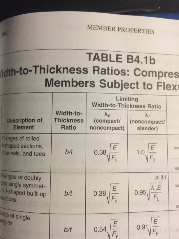
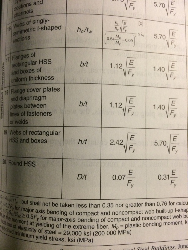
I think KootK has covered most of the basic points in his listing above. Add to his #’s 1, 2 & 3; give a little thought to how you support the 4" pipe at the ends, and what portion of the bending and torsional moments go to each support. Are they fixed or simple supports? We all understand the beam and bending moment and shear thing. But, re: the torsion what does twisting compatibility at the load pl. have to do with the problem? RE: Koot’s #’s 4 & 5, I’d add; conservatively, I’d resolve the torsional loading from the pl. (40kN)(100mm) into two lines of weld (reactions) about .75 or 1" long and 100mm apart, as a back span on a cantilever, about what he suggested. And, I would size the weld terminations somewhere near the size of these reactions. Then I’d size the girth weld to take (40kN)(100mm)/(weld arc length)(50mm), a shear flow per mm of weld. I don’t like the weld terminations on your detail, particularly the one nearest the load, acting in very high tension and some prying. There is just no nice way to terminate this weld on your detail. I would likely put a 30-40mm wide flange on the top of the load pl. so I could weld this flg. pl. to the pipe and protect the girth weld termination, which should stop short of the flg./pipe/load pl. corner. I might also put the same flg. on the bottom of the load pl. to take the compressive bending loads, pl. buckling issues. D/t is an important ratio as relates to the pipe buckling, take a look at a good Strength of Materials or Theory of Elasticity text book.


