Continue to Site

Eng-Tips is the largest engineering community on the Internet

Intelligent Work Forums for Engineering Professionals

  • Congratulations waross on being selected by the Eng-Tips community for having the most helpful posts in the forums last week. Way to Go!

Torsion at bean with pinned ends 1

Status
Not open for further replies.

BAGW

Structural
Jul 15, 2015
392
Hi,

I am confused about concept of torsion in beams with pin ends. When the beams are attached with just a shear connection (pinned)how can the beam resist torsion? Wont the beam be unstable under torsion load? So what scenario does the AISC design guide case 3 refer to?

Thanks
 
Replies continue below

Recommended for you

DG9 refers to a "torsional pin" as free for warping, fixed for twisting, which often causes confusion. If a simple shear connection can resist the torsion depends entirely on the loading applied, but all standard connections provide some rotational restraint at the ends of the beam.
 
Others may not agree, but this is how would I handle it for an edge beam, with torsion derived other than eccentricity.

image_jq5cmw.png
 
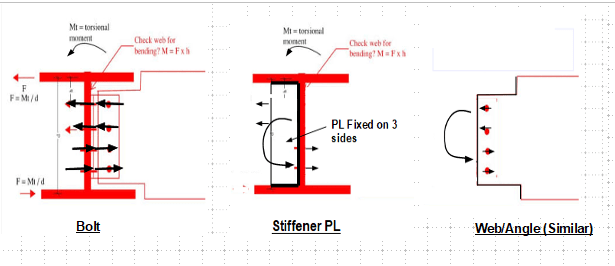
If I have to design a connection as fixed for torsion, can that be achieved with a end plate connection? Similar to end plate moment connection? In that way flanges are attached rigidly at that point. Or any additional detailing is reqd, like adding plates on either side of the flanges (create like a box section)
 
BAGW said:
@ human909 I may or may not run into this on a project. I am trying to convenience the arch to get away from the loading scenario which causes torsion.

I think you mean convince, not convenience. In your earlier post you indicate dimensions d and h. I believe d = h. Please correct me if I'm wrong.

You are illustrating compatibility torsion which the code states you do not have to consider in your design. There is a slight rotation because the supported beam rotates. If the supports are torsionally stiff, there will be a moment at each end of the supporting beam. It is not carried by the web; it is carried by the entire section. If the supports are torsionally pinned, there can be no torsional moment. The beam just rotates to accommodate the end slope of the beam and the bolts resist the eccentricity.

r13 said:
Others may not agree, but this is how would I handle it for an edge beam, with torsion derived other than eccentricity.

I am among 'others'. The stiffener does absolutely nothing to resist shear stresses resulting from torsion.

What do you mean by "torsion derived other than eccentricity"? Is there such a thing? And why should it get special attention?

BA
 
BAGW,

My detail was for the condition below. End plate connection on the supplement beam is not necessary, nor recommended.

image_tqzcya.png
 
BA,

I consider there is externally applied torsion that was implied by the original query. It usually is more severe than the torsion induced by the supplement beam due to eccentricity alone. We do have different view on the stiffener plate. I consider the flanges of the beam will move in opposite direction, as the couple acting on the flanges ±H = T/d
 
r13,

The shear stress is a function of torsional constant J. Warping requires flanges to be connected at each support and is a function of warping constant Cw. So far as I am aware, your stiffener does nothing to change the stresses resulting from either direct torsion or warping, but I'm open to learning otherwise.

BA
 
BA,

Well, as I said, we have different view on this. I don't think we can convince each other, so I cease my case :)
 
A single plate stiffener does very little to restrain warping in a torsion joint where one is trying to introduce a fixed torsionally restrained connection.

If I remember correctly AISC Design Guide #9, recommends a channel that fits snugly between the flanges and is connected to the web at the same time and is welded all around except at the root of the flange web connection would provide more warping restraint.

Secondly, a pinned connection with very limited moment capacity will not prevent the deflection of the W section of the torsionally loaded beam as suggested by r13. A box section HSS for the torsionally loaded beam with a fixed moment restrained connection at both ends would be more successful.

Note, this solution will be more expensive in both materials and labor.

Jim

 
BAGW said:
If I have to design a connection as fixed for torsion, can that be achieved with a end plate connection? Similar to end plate moment connection? In that way flanges are attached rigidly at that point. Or any additional detailing is reqd, like adding plates on either side of the flanges (create like a box section)
As mentioned this can be achieve with a simple shear plate. Sure an end plate connection will be more stiffer and have higher torsion capacity but that isn't any good if you beam lacks torsion stiffness.


This thread seems to have run all over the place. Though like many such threads a few pertinent aspects are raised, a few disagreements on principles and a bunch of disagreements about terminology. I'll try to recap my take and highlight some aspects that haven't been adequately discussed. What I don't think has been emphasized enough is RELATIVE stiffness.

-A theoretical pin does have torsion restrain
-Pretty much all shear connection designs that are modeled as 'pins' have torsion restraint aka shear plates
-Not only that, the torsion restrain provided by a shear plate is 'significant'

'Significant' obviously needs to be qualified/quantified. I claim it is significant because the stiffness of a shear plate connection against torsion is typically significantly higher than the beam to which it connects. A quick check shows typical I-beam with a typical span is an more than an order of magnitude less stiff than a typical shear plate. The torsional capacity of the shear plate isn't too much different from the member it supports but capacity is pretty moot as rotation is the controlling criteria.

Of course if your structural design really does impart significant torsion on a member then your really need to make some other decisions beyond the end connection. Ideally you should endeavor to remove the torsion and if that isn't possible then change reconsider your member choice because a I-beam is far from ideal. A circular hollow section is the obvious choice, these are used all the time for cantilevered street signs.
 
Status
Not open for further replies.

Part and Inventory Search

Sponsor