Dear Experts,
We are currently working on a tie-in for a 10" x 10S SS316L pipe to an existing 24" x 10S SS316L header in a chemical plant, designed in accordance with ASME B31.3.
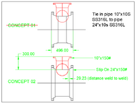
Please see the attached sketch for two proposed concepts.
We are facing two main concerns:

Thank you very much.
We are currently working on a tie-in for a 10" x 10S SS316L pipe to an existing 24" x 10S SS316L header in a chemical plant, designed in accordance with ASME B31.3.
Please see the attached sketch for two proposed concepts.
We are facing two main concerns:
- Project Specification requires Weld Neck (WN) flanges only.
However, due to site constraints, there is insufficient clearance to install the tie-in using a WN flange as shown in Concept 01 (required straight length ≥ 496 mm, which is not available). - Concept 02 uses Slip-On flanges, which allows us to perform the tie-in within the available space.
However, it results in a very short distance between two circumferential welds – only 29.23 mm weld-to-weld. This raises concerns regarding:- Heat Affected Zone (HAZ) overlap
- Residual stresses
- Possible metallurgical degradation in the weld region
- Has anyone encountered a similar situation, and how was it resolved?
- Are there any acceptable practices under ASME B31.3 or recognized industry standards to justify this weld spacing?
- Would performing additional NDE and/or localized PWHT be sufficient for mitigation?
Thank you very much.