Continue to Site

Eng-Tips is the largest engineering community on the Internet

Intelligent Work Forums for Engineering Professionals

  • Congratulations waross on being selected by the Eng-Tips community for having the most helpful posts in the forums last week. Way to Go!

threading to distribute stresses at cylindrical aluminium / steel interface? 1

Status
Not open for further replies.

learningallthetime

New member
Jul 10, 2016
16
rod_bar_ncumbv.jpg


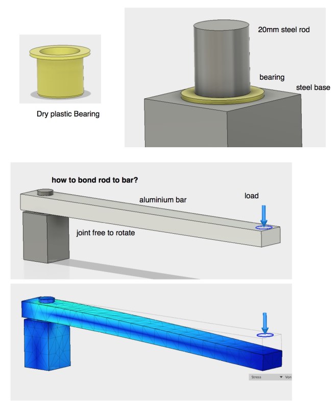
A 20mm steel rod is held vertically by a dry plastic cylindrical bearing such that it can rotate freely in the horizontal plane.

An aluminium bar with a 20mm hole in it is slipped onto the rod and, supported by the bearing below, can rotate freely in the horizontal plane.

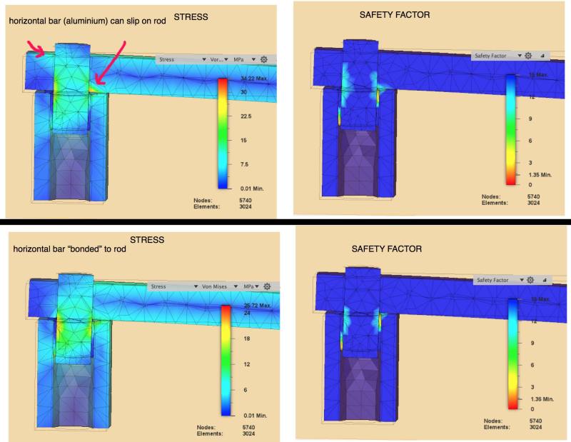
The bar must support a load and in order to distribute stresses at the interface between the aluminium bar and the rod it would be best if they were bonded.

What are the options for bonding the aluminium bar and the steel rod? Or other means for reducing stress concentrations under load?

Should I consider mild - rather than hardened - steel and thread the rod?
 
Replies continue below

Recommended for you

I suggest you look at the various methods used on bicycle cranks. A short taper and a bolt to apply axial compression might be nice.

Cheers

Greg Locock


New here? Try reading these, they might help FAQ731-376
 
Or you could use an automotive hub unit bearing with an aluminum arm attached. Jimmie sent me.
 
How high are the stresses under the existing load?

What is the attachment assumed in your model?

In your analysis Are the highest stresses in the (hardened steel?) rod ?

What does the plastic bearing think of all this?
 
GregLockock, @BrianPetersen Sound real world suggestions. Love the idea of a taper. Trying to figure out how to model that with pre-tension.

@Buggar: sensible as ever this remark. Need something smaller, however, and to find room for encoder and slipring (not mentioned here).

@Tmoose Stress scale just about visible in below image. Point of concern are those in the aluminium bar (red arrows) which seem reduced in the case connection with rod bonded rather than slipping.

Plastic ring used in this model has max tolerance of 35MPa, but that's the lowest rated of the Igus Dry-tech 20mm bearings. Also steel rod will pass through another similar bearing lower down....

Mostly concerned about the Aluminium to as to reduce the chances of deformation in case someone mischievously overloads the system. The combination of machining & installed electronics (not discussed here!) make it relatively costly whereas the plastic bearing could cheaply be swapped out.

interface2_tf40ke.jpg
 
You could press the steel rod into the aluminum bar. ... but I don't trust that joint. It looks like something that will disassemble itself upon being loaded. You seem to be relying on a short bushing to transmit and resist what looks like a fairly large moment.


Mike Halloran
Pembroke Pines, FL, USA
 
Yeah it's fugly, to use a handy expression. I couldn't give a monkey's about the FEA problems with analysing tapers since there are known good analytical solutions. Aluminum on steel is usually nasty.

Cheers

Greg Locock


New here? Try reading these, they might help FAQ731-376
 
@MikeHalloran those are just CAD models with "bonded" defined in software.

In "reality" the rod will reach downwards further and above will be flush with the top of the horizontal bar.

I did have a prototype quite similar and surprisingly the bar didn't seem to work upwards under load, though I couldn't be sure.

Nevertheless the plan is to have the rod fixed in the aluminium and looking for ideas.

Have seen people fixing aluminium to aluminium by heating the female half in a furnace to expand it, then inserting the male.

@GregLocock where do I look to better understand how tapers work mechanically? (You might have guessed I'm not a pro. mech. engineer.)
 
Be aware that a threaded joint is not the same as "bonded". (The threaded joint has one DOF - rotation about the joint axis). Consequently the threaded joint will not solve the stress concentrations shown in your FEA in the way the "bonded" FEA joint does. A tapered thread might be an exception.

je suis charlie
 
I would add a flange to the pin, and bolt the aluminum arm down. Taper is an added bonus, but not necessary in this case.
 
I would go with a taper like a bike crank arm and a single central bolt. A bit of lube on the taper will minimize fretting and ease disassembly.
Making the Al bar thicker, even if just near the joint will help greatly.

= = = = = = = = = = = = = = = = = = = =
P.E. Metallurgy, Plymouth Tube
 
Status
Not open for further replies.

Part and Inventory Search

Sponsor