Tek-Tips is the largest IT community on the Internet today!

Members share and learn making Tek-Tips Forums the best source of peer-reviewed technical information on the Internet!

  • Congratulations MintJulep on being selected by the Eng-Tips community for having the most helpful posts in the forums last week. Way to Go!

Teaching Load Paths Used in Structural Engineering Discussion

Ron247

Structural
Joined
Jan 18, 2019
Messages
1,390
Location
US
Note: this thread may start and stop periodically as I see people’s comments and then see if I have other needs for input.

From a prior thread, the topic of Load Paths (LP) came up. I tried to recall when I first heard of them and started practicing tracing them. I arrived at the BS degree level did not teach them and none of my BS level textbooks even have a reference to them. I do recall hearing of them while taking my Master’s. I looked online and found some instructional videos and watched 2 or 3. One was an hour long from a university lecture. The structures in that video were more complex than you get in a BS degree so I assume it was a Grad level course. One was a skyscraper with floors that cantilevered back to a “central” core for stability. Big, but not complicated in terms of load paths. The other 2 videos had very simple and symmetric structures they traced. Since I feel LPs are important for students to understand early in their training, it started me thinkng about them.

I tried to think of how I would explain LPs to a Junior level BS student. I arrived at the basic definition of a LP that I use is somewhat common for experienced engineers, but it can be confusing to students. I intend to keep using it in the future, but not when explaining to novices on the subject.

For both experienced engineers and students, I am interested in what your definition of load paths is and when you recall first hearing of them. I am also curious what answers you get to the following 2 Free-Body Diagrams if you applied your definition to the task. While these 2 are simple for experienced engineers, they are more complex than the examples used in the videos I watched.

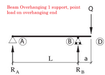
The first is a Simple Span Beam.

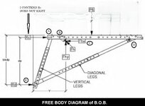
The second is a Bridge Bracket used on new bridge construction to form and pour the outer overhang such as gutter and guardrail areas. Note that I do not think reaction Rc is truly present and definitely not present on downward arm loads. The bracket has a single point load called P6. Trace the paths based on the letters shown at the joints and load application. Points B and E are the only 2 places where the bracket either mechanically attaches (B) or bears against (E) the bridge girder.
1752856082921.png


1752856103142.jpeg
 
loadpaths are simply that ... what path does the load take ? how is the applied load and it's reaction linked ?

Free body diagrams are a different matter. The struted wing(?) you show is Wrong; there needs to be a vertical reaction at D. And there absolutely is a compression at C.
The test for sketching a FBD is "is the a reaction for each applied load direction ?" ... in this case the applied vertical load needs a vertical shear reaction (D is the logical place, as the strut carries this from the wing) and a moment reaction (a couple between C and D). This is the first step in creating a FBD ... sketching the reactions. The second step, to finalise the FBD, is to quantify the reactions so that the body is balanced. Then it is a FBD ! (IMHO)

In your case, the vertical component of the strut load is P6 which is reacted at D, together with the horizontal component of the strut load which is reacted at C and D. At C, Rc is -ve for a reaction or +ve for a load ... that is a pretty massive concept to teach ! Similarly at D, Rd (which is inclined along the direction of the strut) is a +ve reaction and a -ve load ... clear as mud ??
 
Last edited:
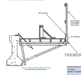
Thanks for the response rb1957. Below is the drawing from a supplier of that bracket. The short wood wall is what the wheel of a screed machine runs on. The wheel load from the screed is generally around 1,000 lbs = P6. The bracket attaches to a concrete girder.

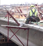
Also, there is a photo of a bridge under construction. In that photo, the brackets are being installed. The bracket is installed completely by the 2 guys on the deck. No one is below where the bottom joint is located. Note the diagonal rod running up to the concrete girder. That is location B on my sketch. I agree, they look like a serious accident waiting to happen. That is why I used it in my example. It can fool you at first glance, it did me years ago until I rigidly applied load paths to it. I have seen many of your responses in other posts and know you are well-schooled in topics like this, but take a 2nd look if you will.

1752866996444.png


1752867127267.png
 
Last edited:
not my business, but wow !

in the drwg ... this is some temporary structure ? to meet OHSA requirements ???? (which would be a horizontal load (?) of X lbs (maybe 200 lbs, maybe 400 lbs ??) ... not much load, but not much structure to carry it !??

maybe the key is (in the picture) that little diagonal brkt ? or maybe this structure is preloaded into the concrete beam ? (or easy removal ?)

A key part of teaching structures is looking at the structure an seeing our simple beam models ... a simple overhanging beam, a wheelbarrow, a simple truss, a more complicated truss, ... then hit them with indeterminate structures (a chair with 4 legs on the ground !!) ...
 
Temporary overhang bracket to pour the gutter and guardrail on a bridge. You have driven under thousands of these over the years if you are anywhere near highway construction. These a spaced from 18" to 36" on center for most every modern bridge.

Not really pre-loaded, more like attach and tighten the nut I think.

To be honest, what I saw in those LP videos were poorly worded explanations in some cases. The poor wording created misconceptions about load paths in IMO. Makes it hard to intuitively learn LPs. The one most applicable to the bridge overhang bracket is "until the load reaches a reaction". It implies that load is done. It has reached a support. More accurately, "the reaction only absorbs the component of the force it is capable of absorbing. The remainder of the load then continues on until it finds a reaction capable of resisting/absorbing it or creating what it needs to be stable". A mouthful but more accurate.
to meet OHSA requirements
The last ones I reviewed were USDOT and state projects.

a chair with 4 legs on the ground
I always get that 4-legged chair that only 3 legs touch the ground. Goes with my table with the same situation.😊
 
I think of load path as "how do forces get to the foundation?"

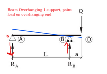
Figure 1, when you apply force Q at location D, point B will behave like a fulcrum with location A trying to lift up. But from support conditions we know A is restraint in horizontal and vertical direction, but location B is restraint only in the vertical direction. Thus, we can say B will in compression and A in tension.

Also, the load is closer so location B so the shearing at B (in the beam) will be higher than A - beam's shear forces. For moments I typically try to use deflection shapes to explain moment diagrams since the virtual method seems to be complicated to newer grads.

Screenshot 2025-07-18 160256.png


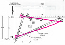
Figure 2- what happens to the "truss" member when force P6 is applied? We get the deflected shape I have drawn. Beam C will be stretch so it will experience tension, at the beam stretches due to bending (force pushing it down), the brace will also shorten causing axial compression in it. As a result, the beam transfers some of the load in the horizontal plane and the brace will do the rest. Something important is how the angle affects the force in the brace from what we know from statics so bad angle can cause a 2x stress in the same load path.

I always try to use deformation to explain load path. For loads on slab, I once tried the water draining on a slab analogy.

Screenshot 2025-07-18 161122.png
 
Bulb, I agree, the SS beam is an example of how the internal forces due to the deformations from the applied force can "continue" to another reaction once they have encountered one reaction because they still insist on stability or collapse. Since Point B was not capable of supplying a resisting moment to counteract Q*a, and there were no fixed joints, it created the couple it needed by enlisting the help of Reaction A. That is why I was uneasy with "the path the load travels until it finds a reaction". It implied that the load path stopped at B because it found a support. Those videos showed one force, one reaction one load path illustrated. They never mentioned that there was MORE than 1 path created. This is 1 force, 2 reactions. So for me, the paths are either DB and DBA or DB and then it continues on as BA. Each path must start at a load and end at a reaction. In this case, 2 load paths were generated.

Another statement I have seen several times is "the shortest path" or the "most efficient path"". That also would imply it is singular and stopped at B. Definitely, DBA is not the shortest path.

The bracket is a good example of applying deformations to help visualize the paths. In your bracket sketch, is location A acting as a reaction?
 
When it comes to load path I think of it in two ways, the conventional and unconventional load path. The conventional load path is the "easy" framing where you load at structural system and distribute the load (ratio and proportional) by how elements are connected. Say, a slab sits on beam, then we definitely know the load will be transfer into the beam and then to whichever column supports the beam.


Load-path[Engineersdaily.com].png


Then you have the unconventional one where understanding statics and member stiffness comes to play. A typical example is a cable-stayed bridge where the load goes from the slab/deck to beams and then to cables in tensions before columns or caissons.

For stiffness, you can play with this in any FEM application. {F} = [k]{U} meaning the stiffness affects the force. Try applying a 1 kip load midspan of the beam with both column members the same. You'd get 0.5kips in each column. Once you change the stiffness of one column significantly, it all changes with the stiffer column have a reaction move than 0.5kips

Screenshot 2025-07-18 182021.png


Another statement I have seen several times is "the shortest path" or the "most efficient path""
This is from a design perspective. Stiffness of a member is inversely proportional to length...... eg. Take two scenarios of a simply supported 2x8 lumber. One has their supports spaced at 20'-0" and the other set-up has their supports at 8'-0". The 8'-0" will transmit load over a shorter so it will have a lesser deflection than the 20'-0" supported lumber. Additionally, for a longer path you could accumulate lots of load (lateral system) which will result in bigger members and connections /detailing.

I would recommend Load Path! The Most Common Source of Engineering Errors.PDF[ Youtube - Load Paths! The Most Common Source of Engineering Errors]
 
The bracket is a good example of applying deformations to help visualize the paths. In your bracket sketch, is location A acting as a reaction?
Yes, I was considering as a reaction since I am considering that location as an attachment point.
 

Part and Inventory Search

Sponsor

Back
Top