Continue to Site

Eng-Tips is the largest engineering community on the Internet

Intelligent Work Forums for Engineering Professionals

  • Congratulations 3DDave on being selected by the Eng-Tips community for having the most helpful posts in the forums last week. Way to Go!

taking out rafter thrust with roof diaphragm

Status
Not open for further replies.

struct_eeyore

Structural
Feb 21, 2017
268
Hi all,

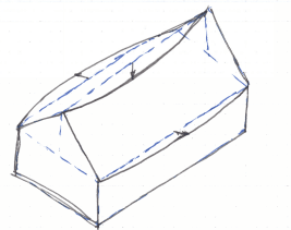
When designing a house with a rafter roof, bearing on an unbraced wall, how legitimate is it to use the roof diaphragm to take out the rafter thrust and transfer it to gable end shearwalls? - and in the process brace the wall? I have previously always been instructed to use collar ties, or find a way to brace the wall below. It appear to work on paper; is there something else I am missing?
 
Replies continue below

Recommended for you

The ridge beam may also be designed for flexure. Otherwise, it will sag.

image_bhaa2y.png
 
I have seen it work long-term in practice and I have seen it fail epically. I always provide some mechanism other than only the roof diaphragm.
I am guessing if it works on paper, you are doing something wrong.
 
Look at each side of the roof as a thin beam laying on an angle. Pretty darn stiff when the roof is staggered plywood sections. Works for me.
 
If roof diaphragms are to be used as suggested, they must be properly designed and constructed. This means specifying chord forces and connection details, connection to the gable wall at each end, strength of gable wall to handle diaphragm reactions and deflection of diaphragms and shear walls when applicable. To ensure proper construction, special inspection is needed. Unfortunately, it is not always provided.

BA
 
I have done this before on a very bespoke timber roof. It took 2 layers of stagger jointed ply, very regularly spaced long screws and a bolting detail into the concrete gable walls.

Thankfully the contractor fully understood it - which is a rarity over here...and did a great job of it. Still standing today!

Obviously this doesn’t work unless its anchored to the gables. You’ll need to follow the load path right through in the calcs. Watch the interface shear between ply and rafters - that will dictate screw centres.
 
I don't understand how this makes any sense. Assuming the plywood diaphragm does not have stiffness out of plane, the direction of resistance provided by the diaphragm is opposite the direction of thrust, thus the roof is not "bearing" on the unbraced wall - the unbraced wall is doing nothing except insulating the occupants. The entire gravity load of the roof is supported by the sheathing resisting twisting. I guess is could self support like that in real life to some extent.
 
AaronMcD,

Roof diaphragms act like a folded plate spanning the length of the building and taking the place of a ridge beam. Each exterior wall carries approximately one quarter of the roof area. The top of wall cannot spread very much but does spread a little because the ridge deflects downwards allowing the top of wall to deflect outwards. Roof rafters span from wall to ridge line, keeping the roof line straight.


BA
 
My biggest problem with this type of system is that not many people would think that replacing some partially rotted or damaged roof decking would cause a collapse of the building.
 
Is everyone using this type of system assuming the diaphragm roof plane is flat? Add snow to the roof and your diaphragm gets a bow in it. That causes PDelta. While floors have similar issue (they are not truly flat) they tend to be less bowed than a roof. I am sure this can work provided the entire system is thought out and connected properly. Let me thrown in some thoughts you need to include:
1. Top Plates and Cap plates on the wall had better have their joints staggered. I already saw one with a 2" difference in joint locations. The wall noticeably jutted out at that area and wall sheeting was holding the chord together. Thankfully they nailed into the top and cap rather than just the studs.
2. I saw the post stated "collar tie"-we already had a post on that issue-I think you mean rafter tie. There is a major difference in some codes about the meaning of those 2 terms.

 
Thrust comes from deflection of the ridge, whether with or without a robust ridge beam. For a diaphragm to reduce this, it has to reduce the deflection potential of the ridge. RPMG shows it in their photo. That is difficult to do with a diaphragm. Would be a lot easier to beef up the ridge beam.
 
My bet is the roof shown by RPMG is an old one with boards for the sheathing, not plywood. All of those I have built with plywood, no ridge beam, did not sag.
 
Based on the 105 siding (if it is wood) in the picture, I would assume it is 1x6 or 1x8 decking. If it is vinyl, it would be unknown. I have seen problems with plywood sheathed diaphragms but I do not think they were designed by anyone. Incidentally, good aspect ratio is the main reason someone can build one without design and it works, but later another person takes their advice and builds one with a poor aspect ratio that does not work so well.
 
@ RPGM - just to clarify, the system that I have does not rely on a ridge beam per se - I have one to provide a wide face for the rafters to butt up against, but the beam itself does not bear anywhere, so no flexure.
@ BA - I think that not being able to stagger lap the plywood across the ridge would make the folded plate analogy unlikely. I would think the roof acts like two independent deep beams, sloped at whatever angle, shearing at the gable ends, and all the bearing being taken out by the rafters at the exterior/bearing wall.
 
If I'm reading the responses correctly, it sounds like the roof diaphragm can provide adequate support if it is designed, detailed and constructed properly. The problem becomes ensuring that all that takes place, especially the proper construction. The attention to detail and accuracy necessary to get an adequate connection of the sheathing to produce continuity of the whole diaphragm isn't typical for building construction, especially residential (at least what I've seen). The construction would need to be done carefully and watched closely to ensure the nails or screws, especially at the joints between panels, hit the 2x underneath, to produce the rigid diaphragm. The amount of care and oversight required for the construction is likely the reason it's unusual to have it designed this way.
 
And remember, the flatter the roof, the greater the "amplification" of vertical forces into in-plane diaphragm forces.
 
Will this have a continuous ridge vent? Not sure it affects any thoughts on this.

the ridge beam sees load by the walls trying to spread out, and will see unintended flexure. A non-structural ridge will just deflect, or in your case rely on the diaphragm to create a deep beam to resist the thrust. As others have noted, the structural ridge beam, if a reasonable length, is a simple solution, and hard to screw up.
 
A plywood diaphragm is flexible per ASCE7 because the nails bend.
 
Status
Not open for further replies.

Part and Inventory Search

Sponsor