Hello!,
Please caution, proper symmetries simplification depends of the nature of the real problem to solve, for instance:
1.- If your problem is a simply
2-D Solid PLANE STRESS where SIGMA_Z out-of-plane is zero by definition (not STRAIN_Z = 0) as well as DISPLACEMENT in Z is zero, then is correct to studY 1/4 of the model using plane stress CPLSTS4 QUAD 4-nodes elements (only TX & TY DOF), and of course the applied load is 1/4 of full load.
Plane stress elements are two-dimensional elements with membrane only stiffness and in-plane loading. The plane stress element idealization has zero stress in the thickness direction. These elements represent structures that are thin relative to their lateral dimensions and planar.
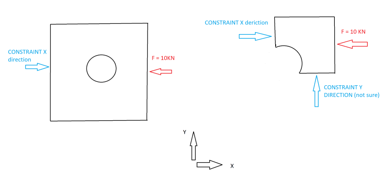
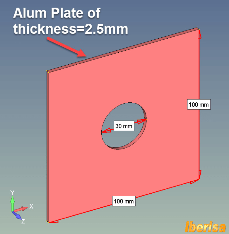
2.- But if you have a general plate situation where buckling could exist due to its low thickness, then the above assumption is not correct at all, I will explain with your example: let's imagine your plate is an aluminum 6061-T6 thin plate with thickness = 2.5 mm only and loaded at both ends with opposed loads of say 10 KN.
The correct assumption is to create the MIDSURFACE of the solid geometry and mesh your problem with 2-D Shell CQUAD4 4-nodes elements with 6 DOF per node, this way you can perform an Euler linear buckling analysis (SOL105) or if you like a full nonlinear analysis activating both geometric & material nonlinearities with any of the nonlinear modules you have (SOL106 or modern SOL401/402), and probably you will receive a big surprise in the limitations you will have in the maximum load capacity of the plate, OK?.
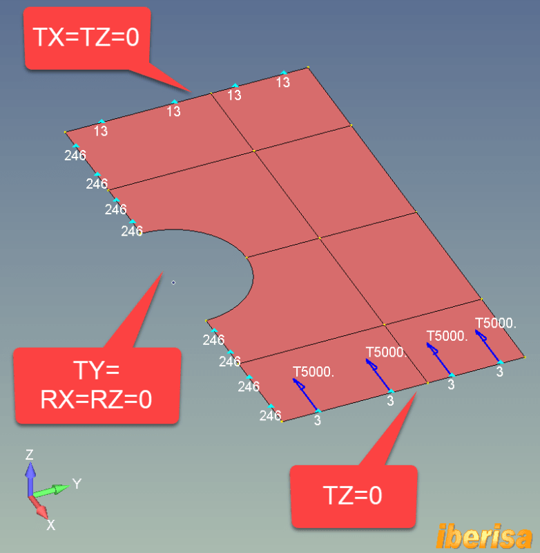
Lets see what happens: The total applied load is FX = -10e3/2 N = -5000N because we study half model by symmetry regarding the Z-X plane, then the constraint to apply to edges in the middle of the plate are TY=RX=RZ=0: we need to constraint not only displacements of translation normal to symmetry plane (TY=0) but also rotations out of symmetry plane, then RX=RZ=0.
In the edges to the left of the plate we apply TX=0 but also TZ=0, we need to constrain the plate in Z-axis direction to avoid rigid body motions.
Also in the edges to the right of the plate we set TZ=0, reasonable assumption, the edge follows the load direction.
LINEAR STATIC ANALYSIS (SOL101)
• The following animation shows the stress results of the linear static analysis (SOL101) of the plate: because not any load exist out-of-plane in the Z direction, then the deformed shape is constrained to the X-Y plane of the plane.
• The maximum resulting vonMises nodal stress is around 140 MPa, if the 6061-T6 Yield Stress = 241 MPa, we have a factor of safety around 241/140 = 1.7, not too bad.
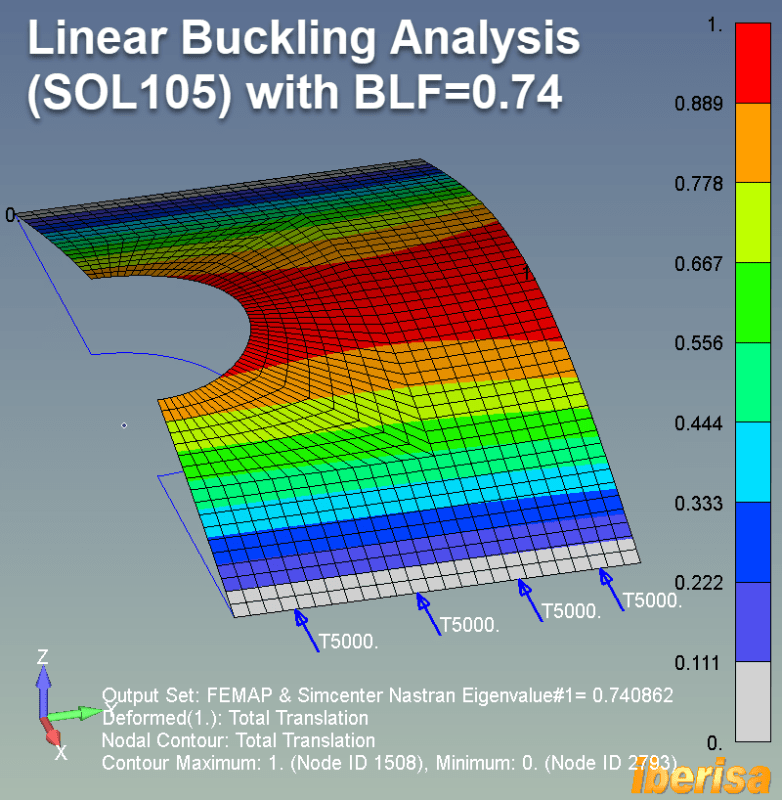
LINEAR EULER BUCKLING ANALYSIS (SOL105)
But what will happens if I run a linear buckling analysis to check the limit load to see if any instability could exist: surprise!!.
The Buckling Load Factor BLF = 0.74, then because BLF<1 this means that the limit load = 0.74 x 10e3 = 7400 N only!!. The plate failed at the original load of 10KN by buckling.
In summary, you see how is life, from the point of view of a simply linear static analysis considering the material properties the solver tells you that no problem exist because the applied load do not exceed the yield stress of the material. BUT Linear Buckling assesses stability under loads; it examines structures for sudden failure modes caused by compressive forces. In chunky thicken solid modes buckling never is a problem, but in thin plates you see that lack of stability is many times the reason a failures in the real life, OK?. Lesson learned: run always both linear static & linear buckling analysis to check that both material & stability pass.
Of curse, real life is always nonlinear & transient dynamic, in case of doubt run a nonlinear analysis and compare result. But the cost of nonlinrear analysis including material, geometry (large displacements effect) & contact is important, this is the reason why many times a linear static & linear buckling is enough when resultant displacements are small and when stresses are well below the yield stress of material.
Lesson learned!!.
Best regards,
Blas.
~~~~~~~~~~~~~~~~~~~~~~
Blas Molero Hidalgo
Ingeniero Industrial
Director
IBERISA
48004 BILBAO (SPAIN)
WEB:
Blog de FEMAP & NX Nastran: