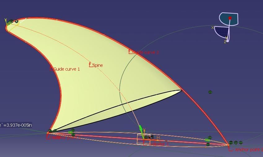
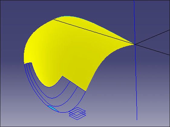
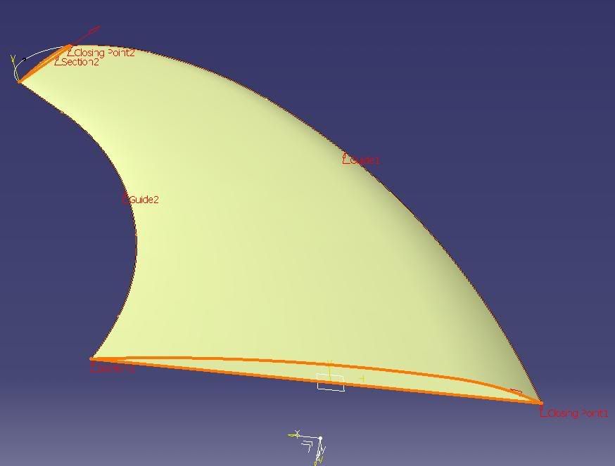
An interesting case, and not uncommon - it's the last bit that's the problem. There is very little to work with: 2 planar curves that appear to be concatenations of circular arcs. The finished part looks as though it is one half of a neutral airfoil.
It's probably safe to assume that a section near the tip will have a parallel scaled down version of the root airfoil - because we're not told otherwise; and whatever this part is for, whether it flies or is a fin on a surfboard doesn't matter.
I've made a look-a-like model where the 2 given curves are splines; in fact the planar fin profile is a 7-point (degree 6) Bezier curve - because of its natural smoothness - see
# at the end. The airfoil section is a simple GSD spline made from 2 endpoints, 2 slopes (tangent lines), and default (1) tensions. What I was after was a 4-sided surface to close this fin.
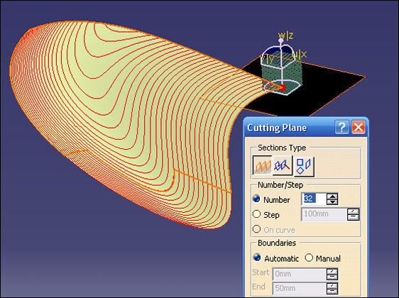
Why a 4-sided surface? Because that's the best (I think) chance of getting a smooth and controlled closing surface - and, there are no radical changes of slope or curvature in it. The curves of the Cutting-Planes analysis in the opening picture are a clue to the closing surface generation.
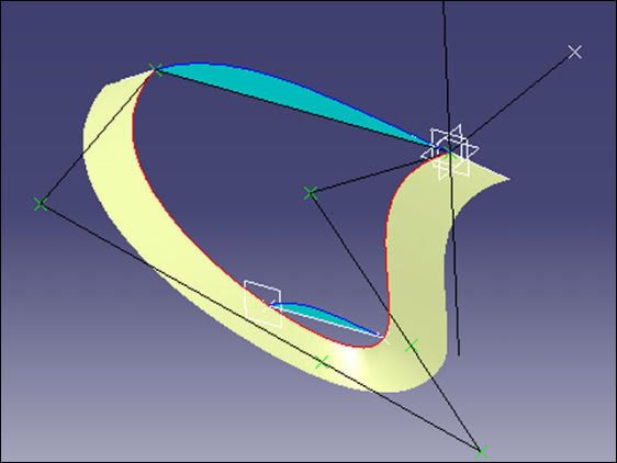
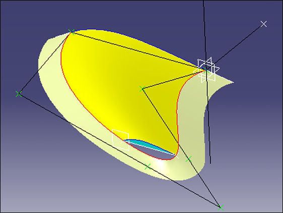
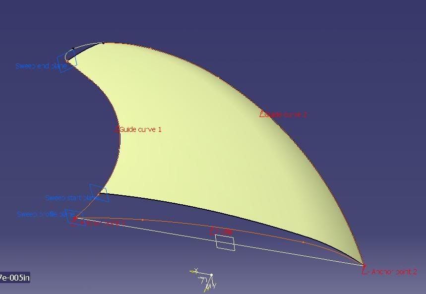
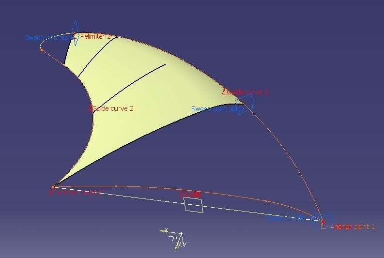
In the second and third pictures a support flange around the fin profile is from a previous construction method, sorry, I forgot to delete it.
A plane parallel to the airfoil one was set up out near the tip of the fin, and another airfoil section made with the same leading and trailing edge slopes and a Multi-Section Surface made using guides from the profile, and the 2 airfoil sections - as they are on parallel planes the spine is linear. The original airfoil could have been swept along the guides, but it's harder then to alter the outer section - if needed. Then the (outer airfoil) plane offset was increased towards the tip as far as possible. So far, this is a
good surface, that can provide information to make its own missing tip.
Then by working
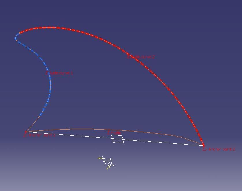
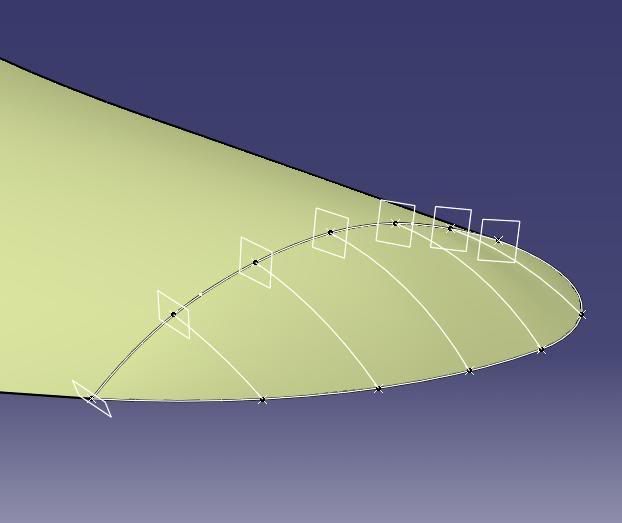
inwards from the tip - into the good MSS surface; 3 equally spaced parallel plane cuts were made through the MSS and the main surface cut away as shown - the outer curve comes from the fin profile. There's enough now information to close the fin with a 4-sided Multi-Section Surface: 4-Sections (on parallel planes), 2-Guides and a Spine that's normal to the fin profile plane - all shown in blue. By cutting the surface this way the 4 sections are akin to map contours of a hill.
The two final surfaces were then joined and analized. By visualisation methods, interrogation (cuts) and so on, checking slope and curvature. We do have the FreeStyle licence here but I'm trying to do this in a GSD situation. As usual there are other ways of doing this but this time I got a better result with this contour method.
# - Bezier Splines: they can be constructed easily by the 'Creating Elements from an External File' method for use in GSD. An understanding and appreciation of these powerful and smooth curves is certainly an asset, whether the user has access to FreeStyle or not. They are very useful in engineering applications - not just in styling. In the first 2 pictures the green control points, connected by black lines, are what defined the fin profile. This could have been constructed using GSD splines, but I preferred the Bezier method - for this shape.
")