Continue to Site

Eng-Tips is the largest engineering community on the Internet

Intelligent Work Forums for Engineering Professionals

  • Congratulations cowski on being selected by the Eng-Tips community for having the most helpful posts in the forums last week. Way to Go!

Surface Profile without Datum

Status
Not open for further replies.

OnlyDale

Mechanical
Nov 22, 2016
3
What would be the best way to tolerance/dimension or even inspect this?

The 0.002 Surface Profile tolerance is without datums, so what would it be checked to? Itself?
I had perhaps mistakenly assumed this would be checked with the datum and XY origin set to the Outside Diameter (datum A), and the inside form checked as a surface profile 0.002 (or +/-0.001) to the datum system.

It would probably be better to have 28.02mm as a boxed dimension instead of 14.01mm.

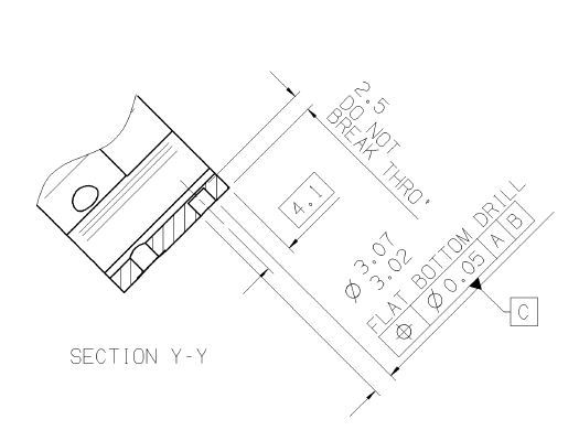
What is key with this part is the parallelism between the opposing flat faces on the internal profile. By internal profile, I mean the flats that are boxed. The 5.8 corner radii is for clearance, as is the slot detail.

Image attached

Thanks in advance for any advice

Dale
 
 http://files.engineering.com/getfile.aspx?folder=15983f7d-ac88-4465-8968-7c63c8e9e420&file=Capture.JPG
Replies continue below

Recommended for you

When applied to a closed contour, profile callout with no datum feature references controls form and size of that contour. The callout defines a 3-dimensional boundary within which surface of the contour must fall. So it is not like checking to itself.

The problem is that technically per the attached snapshot the profile tolerance applies solely to one flat surface of the internal profile, because the all around symbol is missing (see fig. 8-24 in Y14.5-2009).

There are more issues with this piece of the drawing, but that is another story.
 
Yes, all around symbol need to be used here to reflect the design intent, the figure attached looks like your case, the profile callout controls the form and size of the irregular features, you may consider to use position boundary to locate the closed irregular features as shown.

Please note the diameter symbol Ø need to be deleted from the FCF since the tolerance zone is a virtual size boundary.
 
 http://files.engineering.com/getfile.aspx?folder=a4286fa0-0cff-4b89-b0e7-8e3755011af4&file=DSC05521.JPG
Thanks for the replies

The surface profile should only apply to the flats (boxed dimension 14.01) and the 5.8 radii (shown at 12, 3, 6 and 9 o clock on the drawing view).

The 'clover shaped' slot detail in 4 positions isn't included in the surface profile requirements, so should the "all-around" tolerance still apply, seeing as the profile is 'broken'
 
If the profile is meant to apply to the R5.8 then that dimension needs to be basic (boxed). Also I would recommend the between symbol be used to clarify where the start and stop of the profile tolerance applies when not using the all around symbol.

I would seek the opinion of a certified GD&T professional (senior level) if position can be used with profile in this manner (boundary) if the true profile is an open feature. There is only one example in the standard (8.8 Combined Controls - figure 8-24) and it shows a closed feature.

The 4x position FCF of 0.05 [A] [C] is an incorrect use of position. Profile could be used here instead.
 
Andrew -- this looks to be an ISO drawing, based on that use of position, and also how the dimensions are placed above the dimension line, rather than in between the span.
Dale, does the title block say anything about a dimensioning standard?


John-Paul Belanger
 
Yes my comments were all with respect to ASME Y14.5. I have no knowledge about the ISO standard.

Also, out of curiosity, what is your datum C?
 
The dimensioning standard stated is BS 8888.

Datum C is a blind dowel hole, as shown in the screengrab.
Capturec_gcmhxf.jpg


After further discussions, the R5.8 isn't part of the surface profile tolerance, so will remain un-boxed. The surface profile tolerance only applies to the flats.

I agree that instead of DIA 0.010 true position to B|A it should be another profile tolerance of 0.010 to B|A

Andrew, I'm unsure as to why the position tolerance for 4 x DIA 0.05 A|C is incorrect? This is tolerancing a hole to Datum A (Outside Dia) and Datum C (another hole)

Thanks again

Dale
 
Dale,

My initial interpretation of the drawing was that the 4x position of dia. 0.05 A C is positioning the depth of the hole. Position should be used on the size dimension of the hole to locate and orient it. The depth should be described in another way.

If that FCF is supposed to be interpreted as associated with the c'bore diameter then I would say it is correct usage but is shown in a confusing manner (at least for me b/c I am not familiar with BS 8888).

AT
 
Status
Not open for further replies.

Part and Inventory Search

Sponsor