Continue to Site

Eng-Tips is the largest engineering community on the Internet

Intelligent Work Forums for Engineering Professionals

  • Congratulations cowski on being selected by the Eng-Tips community for having the most helpful posts in the forums last week. Way to Go!

stress distribution of a thread in 3D

Status
Not open for further replies.

RBen

Automotive
Jul 17, 2018
3
Hi,

i tried to simulate a threaded connection between a bolt and a nut at the most realistic way, in 3D with applied torque.
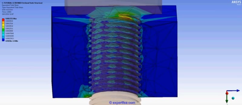
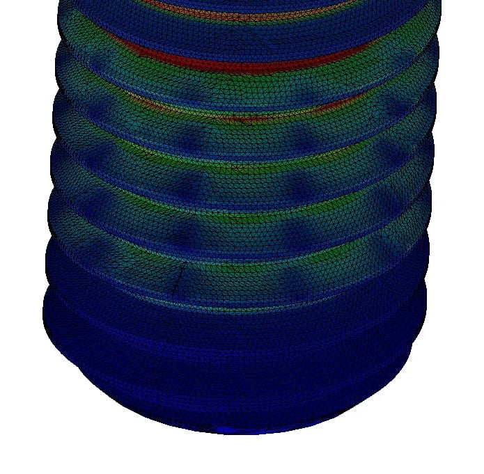
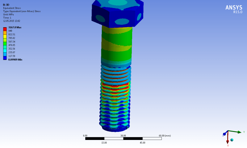
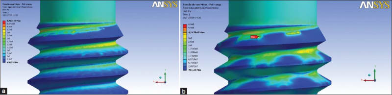
I realised that on this way during the stress distribution a strange Pattern is forming, independently from the simulation settings. (also from friction)
After an investigation i have found that thats also independent from the program, and found many reference, but there were nowhere any comment about this pattern thing.
can someone explain this? i enclose some of the pics/ videos what i have found:
124_v7svli.jpg

02_fkrswd.jpg

CAD_d5hryp.png

EurJDent_2013_7_4_484_120642_u6_wwjzt8.jpg


youtube1 from 1:22
youtube2
 
Replies continue below

Recommended for you

Your mesh is too coarse. Mesh of nut is awful. Try to model axisymmetric case with non-rotating bolt and cylindrical, not helical, thread and get mesh convergence.
 
Hi karachun,

thank you for your answer. As i mentioned before these are not from me, although i also made some simulations with Solidworks to understand this effect and found that the mesh do not have any influence, as we see in picture 2.

Thank you for your suggestions but there can be many cases when only a 3D model with rotation is acceptable for the accurate solution and simplification is not working.
 
If we assume the model is accurate (I am laughing already) there may be some local stick slip phenomenon in each thread so that locally there are high stress part of the thread that are sticking, and lower stress parts that have just released.

Cheers

Greg Locock


New here? Try reading these, they might help FAQ731-376
 
that may be a reale world thing "localised slip" but why would it show up in a FEM ? Mind you I've seen similar repeating patterns where I won't expect them in the real world, things that look like waves propagating though the structure.

another day in paradise, or is paradise one day closer ?
 
"If we assume the model is accurate " being the giveaway. If they've got a realistic friction model and have got everything else right...

Cheers

Greg Locock


New here? Try reading these, they might help FAQ731-376
 
I appreciate the the FEM is probably (no slight intended) fiction, but that aside shouldn't the results be more consistent. I'd assume that he's modeled the two faces of the spiral thread, and modeled a consistent friction ... which "should" give a consistent result.

another day in paradise, or is paradise one day closer ?
 
Hi,
i attached my 3D model if someone has time to check it or give a try.
These patterns are independent from the friction because they are also there with 0. Also when i set up the nut as Rigid body without any deformation. What i have also realised that there is a correlation with the number of the waves and the pitch. If the pitch is lower theres more of them.
 
 https://files.engineering.com/getfile.aspx?folder=712daf06-7892-42d1-ae5d-ff297c59aaf0&file=M12BG.STEP
Status
Not open for further replies.

Part and Inventory Search

Sponsor