Connections can be tricky to model with FEM. There is just so much connection testing out there that doesn't necessarily match up with FEM models. I'm reminded of the slotted web WF connections (tested in Arizona) that were tested extensively as an effort to replace the pre-Northridge connections. If I recall, they tested a number of different variations to try to relieve some of the localized stresses by slotting the column or beam webs. And, the testing never quite lived up to what they predicted using FEM.
Some thoughts about the use of FEM for this type of connection and such:
1) Engineer92's model looks like it's well put together. Hard to tell for sure because there are some limitations to the way RISA renders that makes some things look a little odd in that view.
2) Models like this are best for getting LINEAR results. Meaning that you don't take into account any material nonlinearity. Maximum elastic stress on welds and such. Reasonable for connections that remain essentially elastic through their design life. But, I wouldn't rely on these FEM results to justify something that has significant ductility requirements for seismic loading. R = 3, okay. But, certainly not for SMF, IMF, or SCBF. Probably not OCBF, maybe OMF.
2a) There can be some non-linearity associated with compression only springs at the base plate, but not with any material yielding. I should point out that for pre-tensioned bolts, this is also tricky to model in that there would be compression between the main plate and the adjacent flange / plate to which it is connecting.
3) The RISA plate analysis is not capable of checking buckling. For members and the wall (which is a super-element), the program will account for some P-Delta effects when requested, but not for the pure plate elements. Therefore, you'd want to check the b/t ratios for the stiffener plates to make sure they are reasonable. I believe the AISC design guide on stiffened end plate connections has an example where they check the b/t ratio of the stiffener plate to make sure it isn't subject to local buckling.
The biggest concern about this particular connection I have is related to what everyone else has pointed out. Where those stiffeners connect to the approximate middle of the HSS. My thoughts on that.
4) The RISA model may do a decent job of predicting the maximum elastic stress at these points. Of course, this may end up being a little over conservative.
5) In addition, AISC Table K1.2 has a formula (K1-3 in the 14th edition) t_plate < Fu_HSS * t_HSS / Fy_plate. The idea is that you want plate to start yielding before it can rupture through the wall of the HSS.
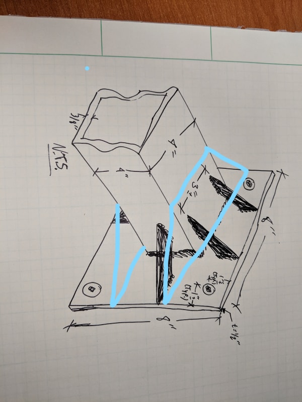
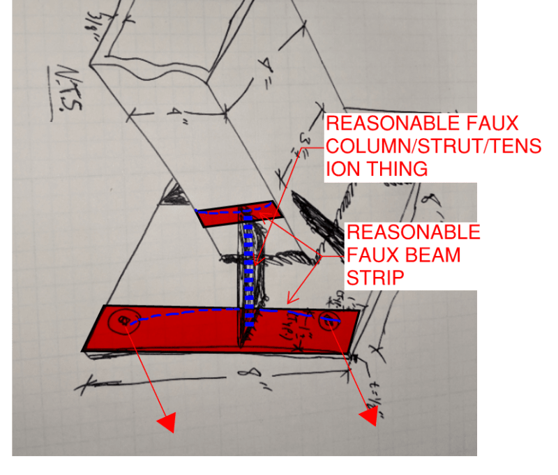
6) I would do something similar to what KootK did for where the stiffener connects to the HSS. Meaning, I would use a representative length of the stiffener. However, I'd personally prefer to take the stiffener force and convert it into a shear and a tension on connection between the HSS wall and the representative stiffener length. Then I'd use the Table K1.2 equations to check it. That way, it's a little more code based and hopefully a little less conservative than KootK's method.
7) I'm not as concerned over the plate failure strip that KootK has in his drawing. Still worth checking. But, I'd say it's more like a fixed / fixed beam at each bolt location.... assuming that the bolts are fully tensioned and the design strip width isn't much bigger than the nuts / washers in that connection. Though I would want to check that the total reaction at each bolt isn't going to overcome the pre-tension.
![[shocked]](/data/assets/smilies/shocked.gif "[shocked] [shocked]")