Ingenuity
Structural
- May 17, 2001
- 2,374
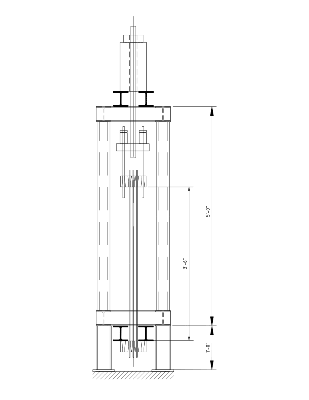
I have designed and detailed a 6 foot tall steel testing frame that shall be used for static testing of post-tensioning strand & wire tendon assemblies. Simple set up of multi-wire or multi-strand vertical tendons, concentric within a steel frame.

I have an immediate need for a 200,000 lb.f test load, but I may design the frame for a possible 400,000 lb.f capacity with modifications to the beam spans/sizes.
A hydraulic center-hole ram on the top beams provides statically applied incrementing loads to the tendon assembly, and reacts upon the top and bottom beams, with load passing into the 4 x vertical columns.
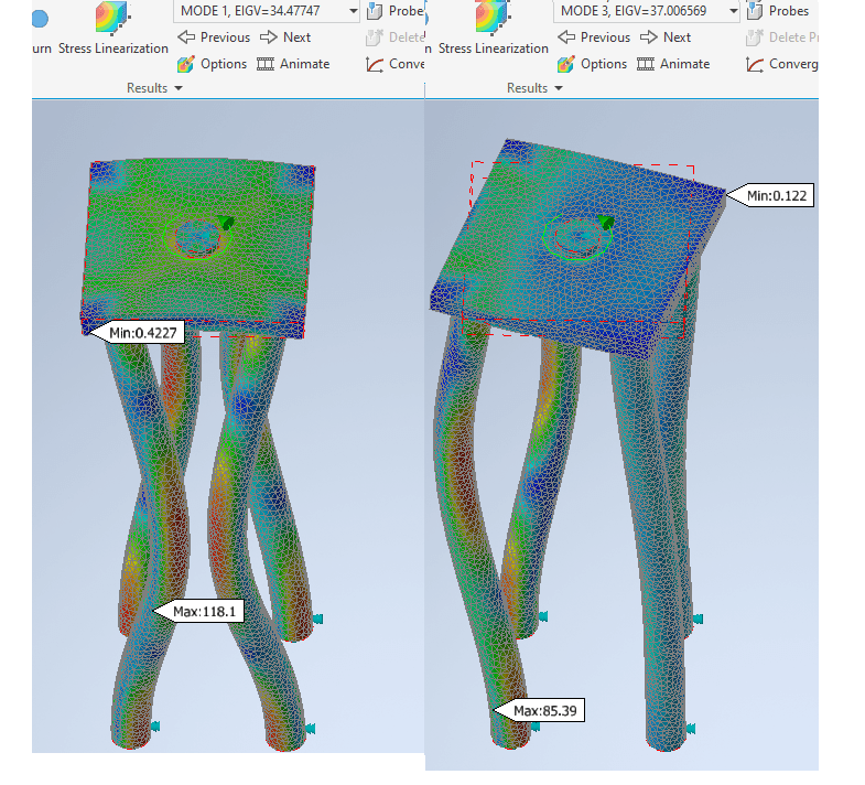
I checked the flexural buckling of the 4 vertical legs - they are 3" XX STRONG pipes, with W4x13 top and bottom horizontal beams, so a nominal axial capacity of 200 kips each leg to AISC 360-16. I need to factor in some accidental eccentricity and check for beam/column actions.
BUT...since the vertically-applied post-tensioning tendon is the source of the applied load, it is NOT possible for a sway buckling mode - similar to a vertical self-centering system. Do you agree?
I need a reality check before I start welding up the frame. Thanks.
I have an immediate need for a 200,000 lb.f test load, but I may design the frame for a possible 400,000 lb.f capacity with modifications to the beam spans/sizes.
A hydraulic center-hole ram on the top beams provides statically applied incrementing loads to the tendon assembly, and reacts upon the top and bottom beams, with load passing into the 4 x vertical columns.
I checked the flexural buckling of the 4 vertical legs - they are 3" XX STRONG pipes, with W4x13 top and bottom horizontal beams, so a nominal axial capacity of 200 kips each leg to AISC 360-16. I need to factor in some accidental eccentricity and check for beam/column actions.
BUT...since the vertically-applied post-tensioning tendon is the source of the applied load, it is NOT possible for a sway buckling mode - similar to a vertical self-centering system. Do you agree?
I need a reality check before I start welding up the frame. Thanks.
![[ponder]](/data/assets/smilies/ponder.gif "[ponder] [ponder]") So what was with those damn imperial units you are using!
So what was with those damn imperial units you are using! ![[dazed]](/data/assets/smilies/dazed.gif "[dazed] [dazed]")