Continue to Site

Eng-Tips is the largest engineering community on the Internet

Intelligent Work Forums for Engineering Professionals

  • Congratulations cowski on being selected by the Eng-Tips community for having the most helpful posts in the forums last week. Way to Go!

STEEL SLOPPED COLUMN 1

Status
Not open for further replies.

mlevario99

Structural
Aug 26, 2008
26
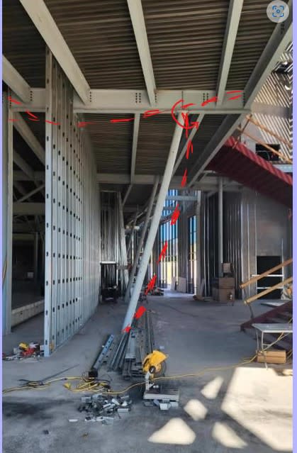
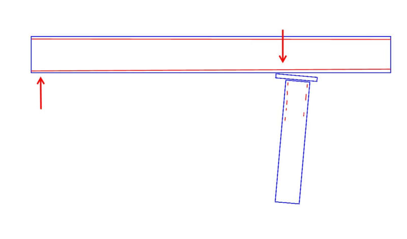
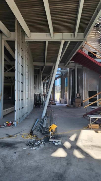
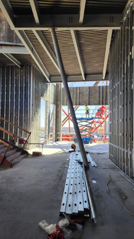
I have a project under construction where we have some slopped columns. They support a cantilever beam condition. The angle of the column is 75 degrees with the horizontal. The grid of the columns is in a radius. The height of the column, from the finish floor to the top of column is 23'-1" is a steel pipe HSS 8.625X0.322. It was noticed the columns is bowing, about 1.5", they use a string to measure. The top of the column has a cap plate with holes so it can be bolted to the beam instead of welded. To me, it seems like during erection the column was forced a little so the holes could fit. I am suggesting to shore the beam, remove the bolts and allow the column to move so it can be straight, then weld the cap plate to the beam flange.

Any opinions on why the column bowed?

I am including some pictures of one column.

thanks


PHOTO_01_qeyh31.jpg


PHOTO_02_tiksbd.jpg
 
Replies continue below

Recommended for you

I would guess it was bent before they installed it.
 
Accidental fixity between the column top and beam, backspan loading wants to rotate the joint counterclockwise partial fixity of the joint is forcing compatibility:
Screenshot_2024-06-07_093710_nk43um.jpg


welding the cap may actually make the condition worsen as the building experiences closer to full design loading.
 
The beam was likely deflected prior to installation so unless the cap plate is very stiff and was at the wrong angle and the bolts pulled it tight, then I don't see it.
 
Run the numbers and see if the column works. Include the P-delta moment in your calculations. What's the stress ratio? If it's small, you're ok. If it's big, you'll need to think about it some more. I'm wondering if the connection plate at the top may have been fabricated slightly off - which could have cause the bow when the bolts were tightened. If that's the case then perhaps the bolts can be loosened (after installing shores) to see if the column straightens out. If it does, then you can install tapered shims and install new bolts.
 
I think this could be due to the connection fixity, as noted above. Or maybe the column is undersized?

Is it just me or does it also look like the beam has visibly deflected? Maybe the beam is also undersized.

Overall, this doesn't look great.
 
The cap plate is 3/4".

When I spoke with the erector, they claimed nothing was forced. But for this to fit perfectly, everything has to be precise.

Any suggestion?


The bean in the picture is a W24x55, with a 17'-6" back span and a 6'-0" cantilever, the column is a HSS 8.625 x 0.322. So, no, the beam is not undersize nor the column.
 
It could also be a combination of all the things mentioned so far:
- Fabrication Imperfection - initial bow
- Installation Imperfection - using the bolts to bring everything in alignment introducing some pre-stress to the joint
- Unintended joint fixity
- Higher than anticipated construction loading?

Everything above combined with P-Delta.

You can likely test some of it by running a quick model with the joint fixed and P-delta (make sure to subdivide the sloped column into about 5 or more segments).
 
cliff234 said:
Include the P-delta moment in your calculations

Actually, there is no moment in the member due to P-delta. This should be an axially loaded member. There will be a shear at the top and bottom of the column to balance the moment caused by the eccentricity between the top and the bottom of the column.

If the column was not forced into the bowed shape, and it was not fabricated with a camber, then my best guess is this is being caused by accidental fixity to the beam as mentioned above.

DaveAtkins
 
I think he was referring to the current p-delta due to the bow
 
It looks like there are several of these sloped columns. Are all of them bowing?
 
mlevario99 said:
IceNine, Yes, some have less bow.

That points to load induced curvature rather than pre-installation "kink" which, presumably, is why IceNine asked.

That said, my first check would be to get a string line on the thing and determine whether the column is bowed or kinked. That piece of information rules some things out.

Is this gong to be an architectural problem? If not, checking capacity ought not be a big deal if this is bowing rather than kinking. All that you would need to do is:

1) Model the frame assuming a rigid beam to post joint.

2) Do a run of the mill column check with the moment from #1 applied at the top.

For the case of load bowing, the instability is the P-Baby_Delta variety which is already baked into the standard code checks.
 
If this was load induced curvature, presumably this would an issue whether the column was straight or slanted. If so, why don't we see this more often?
 
Is that a support just on the other side of the CFM wall as well? I see a bunch of bolts there. If so, that would make for a pretty stiff beam.
 
XR250 said:
If this was load induced curvature, presumably this would an issue whether the column was straight or slanted. If so, why don't we see this more often?

A fine point. Perhaps it is this kind of load induced bowing. More about axial load eccentricity than moment transfer per se. It never ceases to amaze me how quickly fit up seems to go awry the minute things stop being plumb / orthogonal.

c01_cwrcsb.jpg
 
KootK said:
A fine point. Perhaps it is this kind of load induced bowing. More about axial load eccentricity than moment transfer per se. It never ceases to amaze me how quickly fit up seems to go awry the minute things stop being plumb / orthogonal.

Makes sense. I suppose they could shore it up and loosen the bolts and see if it springs back into shape.
 
at 1.5" delta KootK's sketch, and XR250's comments, probably makes the most sense, to get that much delta with no load on the span you'd need to rotate the column end about 0.01 rad (little over half a degree). That beam with 5 kip/ft (WAG) loading only rotates the joint about 0.002 rad.
 
Status
Not open for further replies.

Part and Inventory Search

Sponsor