Continue to Site

Eng-Tips is the largest engineering community on the Internet

Intelligent Work Forums for Engineering Professionals

  • Congratulations The Obturator on being selected by the Eng-Tips community for having the most helpful posts in the forums last week. Way to Go!

Steel plate connection to end of concrete wall

Status
Not open for further replies.

shacked

Structural
Aug 6, 2007
182
I am trying to detail a connection but I am having some trouble2nd thoughts due to the location.
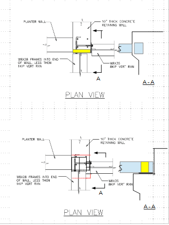
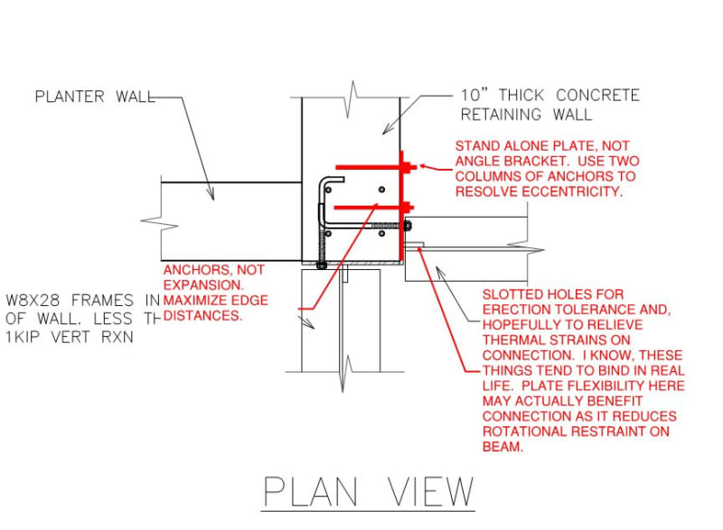
See attached pdf for reference. Basically 2 steel beams at 90 degrees to each other both frame into the end of a concrete retaining wall.
The max vertical load is from the w8x35 that is oriented perpendicular to the face of the wall.

Due to the location of the bearing walls above the centerline of the w8x35 is approx 1 1/4" from the end/edge of the wall.

I realize that due to the eccentric load the top of the baseplate would want to pull away from the wall, but if both plates were welded together the the anchor bolts located at the end of the wall would resist the tension.

I would appreciate your thoughts. (This is a multi story residence)
 
 https://files.engineering.com/getfile.aspx?folder=b97ea36c-e16e-4be0-838b-e01b44e38fb7&file=CONNECTION.pdf
Replies continue below

Recommended for you

for sure the eccentric connection is not good
why not make symmetric anchor bolts ?
 
Suggestions.

c_xkdmme.png
 
1) Take all that follow with a grain of salt. What you've done is about what I would expect to see and, frankly, I'm not sure that I can do it any better. My thoughts will be just that: the stuff that I'd be thinking about if this were my baby.

2) Question: how exposed to the elements will these connections be when all is said and done?

3) Your loads are small, as you've intimated, so my concerns with this connection would mostly pertain to less tangible things which would include:

a) Erection tolerances and the desirability of slotted holes.

b) Thermal, axial strains in the beams that would tend to pull the corner of the retaining wall away from the main body. This would be less of a concern if the connection were within the building envelope of course. This potentially creates another reason to consider slotting your holes (marginally effective movement joints).

b) Water getting behind the connection plates and creating corrosion potential. If these connections will be outside of the building envelope, I'd galvanize.

c) I'd seek to maximize edge distances on the anchors. The installation of the anchors invariably leads to micro-cracking in the concrete if not outright cracking. And that will again tend to encourage the corner of the retaining wall pulling away from the main body.

d) I would actually prefer to see this connection split into two, independent plates as shown below. I feel that would accomplish a few things:

i) more predictable behavior.

ii) more rotational flexibility for the 8kip beam.

iii) less shear perpendicular to edge demand on some anchors with limited edge distances.

C03_ixsluz.jpg
 
Paying homage to the ideas expressed in my last post, here's the WWKD (what would KootK do).

C01_exct4b.jpg


c02_zqsjzx.jpg
 
Thanks for your replies.
Kootk I see how you would handle the beam with the 8kip load and that makes sense. You are moving the A.B. group away from the edge in order to resolve the moment into smaller forces.
I like it.
 

Dear shacked (Structural);

The 10 in thk . implies the retaining wall ht. should be in the range of 10 ft. and the sketch implies the planter wall and retaining wall is not rigid connected. If this is the case, the retaining wall is prone to tip deflection and will transfer loads to the mentioned steel sections.

If i were the designer, i would prefer seat type connection or simple fin plate conn. with slotted holes..
 
Status
Not open for further replies.

Part and Inventory Search

Sponsor