Tek-Tips is the largest IT community on the Internet today!

Members share and learn making Tek-Tips Forums the best source of peer-reviewed technical information on the Internet!

  • Congratulations TugboatEng on being selected by the Eng-Tips community for having the most helpful posts in the forums last week. Way to Go!

Steel Perpendicular Connection

Status
Not open for further replies.

francis_intano

Structural
Joined
Sep 29, 2021
Messages
17
Location
PH
Does anybody know what this type of connections are called? Any references on how to design them?

Perpendicular_Connection_fassog.png


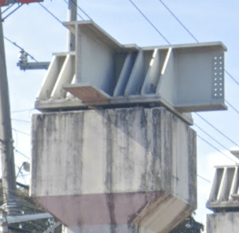
I have a pretty much same structure to design, so I was thinking maybe I could do this scheme too. Any one who has an idea?
 
If you have to ask then you shouldn't be asking.

This applies whether you are a student (this forum isn't for student projects) or an engineer.
 
It's a heavy welded node on top of a concrete pedestal. This is likely a bridge application, where a specific firm will have designed it, in coordination with a fabricator, to a very specific set of loads/codes/requirements. Those huge stiffeners and bearing elements are there for a reason, perhaps seismic.

I don't know the reason, but you definitely need to know why. Start asking questions to your offline peers/leaders first, because a generalized answer from the internet can only take you so far with such a complex arrangement of specialized conditions, heavy welds, and stub beams. For instance, your geographic location alone could validate/invalidate the applicability of anyone's response from this site.
 
@ francis
connection between Steel and Concrete
attached file may be helpful
Link
 
It looks like a steel bearing connection of a bridge steel bridge onto a concrete column.

I'm not really a bridge design guy. But, this connection seems pretty unusual to me. I'd be wary to copy this unless you're getting some advice from an engineer with a lot more bridge design experience.

My guess is that this is NOT the most economical connection / construction. But again, I'm not much of a bridge guy.
 
Looks like a distribution platform for a bridge bearing carrying a very heavy load, probably in the thousands of kips. Given the small dimensions of the column, I would surmise the bearing it is to support is a sliding bearing or a seismic isolator.

In any case, as others have said, you shouldn't be copying the configuration for a different application. This is obviously designed for a very specific loading scheme.

Rod Smith, P.E., The artist formerly known as HotRod10
 
This looks like a one off design to me, so I doubt you will find a cookbook method to design whatever it is. What is your structure and what is the structure in the photo?
 
Thanks everyone! On another look, seems like a specialized design for specific project that I might inquire here locally.
 
Status
Not open for further replies.

Part and Inventory Search

Sponsor

Back
Top