Continue to Site

Eng-Tips is the largest engineering community on the Internet

Intelligent Work Forums for Engineering Professionals

  • Congratulations cowski on being selected by the Eng-Tips community for having the most helpful posts in the forums last week. Way to Go!

Steel or Concrete Moment Frames for Slender, Single-Bay Building

Status
Not open for further replies.

PengStruct

Structural
Jun 9, 2010
39

I'm trying to determine the best type of lateral system for a 9 story apartment building only 17' wide x 60' long. Using a series of closely spaced steel moment frames (R=3) with a couple lines of braced frames seems to work well if I use cmu side walls and hefty concrete elements at the foundations to hold the frames down, or even deep foundations with tensile capacity which may end up being required after the geotech info comes in.

As an alternative which, the architect wants me to consider in order to minimize the floor to floor, I'm starting to look into using ordinary concrete moment frames and concrete shear walls at the core. Before I get too far into this, I'm wondering if anyone has insight into the feasibility of either system for such a relatively slender, single bay in the narrow direction, building with an aspect ratio of about 4.7? I suspect a flat plate will not work and drop beams will be needed between the columns which would end up providing a similar floor to floor as the steel system.

Does anything stand out as pointing clearly to either steel or concrete?
 
Replies continue below

Recommended for you

I like your original proposal of steel moment frames all over. Torsionally appropriate and one of the few ways to achieve a reasonable foundation I expect. If it's architecturally palatable to concentrically brace the two end frames and a couple of consecutive bays on the long side to form a C-shaped arrangement, there might be merit in that as well. If deep foundations are an option, you might be able to swing a central core with flat plate slabs. I'd have to think that you'd need piles to staple that shaft down to mother earth though. And torsion on the foundation would be a thing. How's that for some vague advice?

I like to debate structural engineering theory -- a lot. If I challenge you on something, know that I'm doing so because I respect your opinion enough to either change it or adopt it.
 
Thanks for your response KootK, I've been meaning to get back to you but I've been trying to find some good examples of how to analyze the flat plate for lateral loads. I want to get a good understanding of the lateral capacity of the flat plate/column connections themselves before analyzing the shear walls at the core. I know you need to account for moment transfer through flexure and shear as well as check punching and beam shear. The problem I'm having is finding these slab moments due to later forces.

I read that the Equivalent Frame Method is not to be used for Lateral analysis. If this is so, then what technique should be used? Can you run a portal frame by hand assuming an effective equivalent width of slab to resist lateral combined with reduced stiffness of the slab? If anyone can point me to a good text on analysis methods and modeling techniques for flat plates with lateral loads I would be grateful.

I have a STAAD 3d model running with just columns and plates and the drifts seem reasonable but the dead and live load moments from the slab are not transferring into the columns. I'm going to try to create a stiff zone at the column slab intersection using a master node at the column axis with slave nodes at the column faces and see if that works.

I would like to do the analysis using at least two methods and compare results.
 
I'm finding alot of good information in the 2014 edition of ACI 318 pertaining to my questions. Also ACI 421-3R-15 looks promising as well.
 
I'd like to check that out. Would you mind sharing the clause sections? I'm interested but not quite enough to go digging myself. Some additional points:

1) If you're in a high seismic environment, this lateral system is usually discouraged and sometimes prohibited. End disclaimer.

2) I have experience doing the flat plate moment frame exactly once. It ended up being a bit clumsy in that you wind up with significant bottom steel at your columns all over the place. Kinda kills off the sexy regularity of the system. On the one project, we designed the building to not have concrete shafts. The owner wound up putting them in anyhow just for the feel good factor. It didn't feel to good to me because I felt that invalidated much of my analysis.

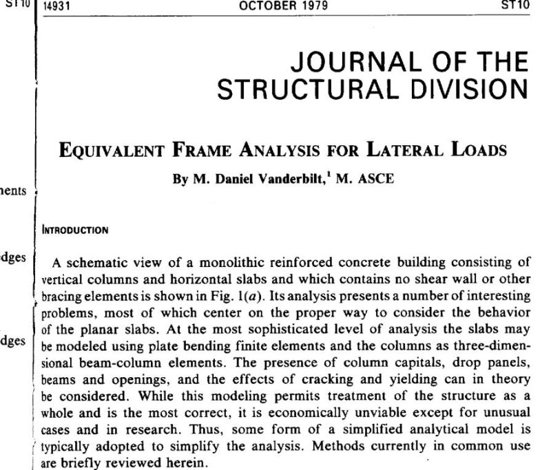
3) I'm the proud owner of a single article on this topic as shown below. That's taking you way back to 1979. I feel that you can use pretty much any analysis tool you like so long as it can be shown to be somewhat rational and accepted. I'd probably be looking at ETABS etc for at least as one of the two methods being considered for validation. I think that the key from an analysis perspective is to capture the whole "moment leakage at the joint" concept as the equivalent frame method and FEM both do.

4) As a matter of pure serendipity, I've been perusing an interesting article dealing with slab-column moment connections: Perhaps you will find it interesting as well. They authors purport to have a lock on a method more rational and more predictive than the classic code version.

c01_tcl2pd.jpg


I like to debate structural engineering theory -- a lot. If I challenge you on something, know that I'm doing so because I respect your opinion enough to either change it or adopt it.
 
I wouldn't think twice about telling an architect that a concrete moment frame won't work for your situation. If it is a residential building, wouldn't you have stairs each end to provide sufficient shear walls?
 
Hokie,

You mean like the ones in the Twin Towers that consisted of 2 sheets of 16mm plasterboard!
 
No, I don't think the towers depended on the plasterboard for lateral resistance. But I was suggesting reinforced concrete shear walls. Or 9 storeys could be done in reinforced masonry.
 

I just discussed the project yesterday with the architect and he's agreeing to go with steel for this job. I told him it would be quicker designing it in steel and that seemed to change his mind. I'm relieved, however, still glad I've done all the preliminary concrete design just to get more familiar with flat plate frames.

KootK:

ACI 318 14 Section 6.6.3 Talks about using 0.25Ig for analysis of flat plates which includes a stiffness reduction factor. However, in ACI-4213R-15, which is a guide to design of two way slab systems, section 7.2 says to use the equivalent beam width model, which results in much smaller section properties. I see no clear direction as to when the different section properties apply. In ETABS, it appears to use 0.25Ig for analysis under wind and seismic loads. Using that coupled with a narrow elev core, I was getting a passable design but would have resulted in huge uplift on the foundation.

This is the northeast, low seismic area so It appears the moment system is allowed, I'm pretty sure I will be in SDC B. Thank you for the articles, still trying to find time to read them.

Rapt & Hokie66: The stairs and elevator are at the center of the building. Now that we're going with steel I'll probably add braced frames at the stair/elev. core to help out the steel moment frames. Hopefully the uplift will be manageable.


Status
Not open for further replies.

Part and Inventory Search

Sponsor