Continue to Site

Eng-Tips is the largest engineering community on the Internet

Intelligent Work Forums for Engineering Professionals

  • Congratulations 3DDave on being selected by the Eng-Tips community for having the most helpful posts in the forums last week. Way to Go!

Steel flange under concentrated load

Status
Not open for further replies.

n3jc

Civil/Environmental
Nov 7, 2016
189
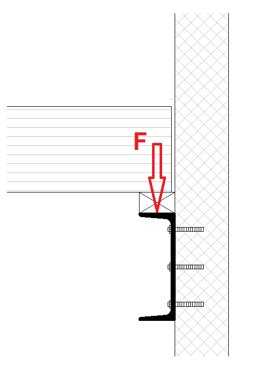
Hello, I'd like to know how do you guys control/check if steel flange/profile is sufficient without stiffeners?
Appreciate your answers.
Regards.
F_cee8g3.png
 
Replies continue below

Recommended for you

well...either you do a (simple) hand calculation or a FE Model


best regards
Klaus
 
Klaus said:
well...either you do a (simple) hand calculation or a FE Model
I think FE is way overkill for that.
I would take the moment as F * 1/2 Flange width and then calculate the section properties based on the web thickness and be done with it.
 
Agree w/ XR250, hand calcs all the way. We'd never make money doing FEA for this type of stuff.
 

Of course....but I have seen FE Calc for even easier situations :)


best regards
Klaus
 
Chapter K Special Design Considerations in the AISC 9th edition describes how to check the need for stiffeners. Looks like it's under J10 in the 13th edition.

Nearly all men can stand adversity, but if you want to test a man's character, give him power. Abraham Lincoln
 
Bagman2524 said:
Chapter K Special Design Considerations in the AISC 9th edition describes how to check the need for stiffeners. Looks like it's under J10 in the 13th edition
I am too lazy to check that reference but my suspicion is that it does not apply in this case as the web is braced by the fasteners.
 
without a stiffener, I would expect the top fla of the channel to rotate and thus reduce the effective bearing length of the wood bm....
 
N3jc:
The NDS code will tell you that you need a min. bearing for that wooden (gluelam?) beam and you have to check the beam and the 2 or 3x bearing member for compression perpendicular to the grain at the beam bearing. Then, what XR250 is suggesting is that you will have a bending moment at the wall, which equals (F)(approx. ½ the flange width) and you should check this bending in the channel web, which is weaker than the channel flange, since the web thk. is generally smaller than the flg. thk. in the ‘k’ area of the channel. You would probably be better off the put two of the anchors up near the top of the channel and one down low centered under the beam. This will help counteract the prying action on the top of the channel as the wooden beam deflects and applies its moment. The anchor cap’y. in pull-out and bearing may actually be the bigger issue. Then, some engineering judgement comes into play in determining the length of channel which acts in carrying the bending moment. Someone who needs FEA to do this calc., for lack of engineering knowledge and ability to do a simple free body diag., probably shouldn’t be doing this problem without some local supervision and mentoring.
 
Status
Not open for further replies.

Part and Inventory Search

Sponsor