Continue to Site

Eng-Tips is the largest engineering community on the Internet

Intelligent Work Forums for Engineering Professionals

  • Congratulations waross on being selected by the Eng-Tips community for having the most helpful posts in the forums last week. Way to Go!

Square Hollow Tube Lifting Calculation 4

Status
Not open for further replies.

patchlam

Chemical
Oct 15, 2015
52
Dear all,

Good day to you all. I am currently calculating the safety working load for my hollow tube spreader beam.

Basically, the hollow tube is in the dimension of 200x200x8 RHS and the two ends are installed with lug. Please find the other details below:

Capture_glgc6p.png


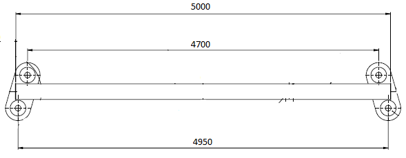
The target load is 36 tonnes and the material of hollow tube is S275 J2 G3

I used the calculator below (Beam Bending Equations Calculator with Ends Overhanging Supports and a Two Equal Loads applied at Symmetrical Locations) and found out that the deflection is more than the allowable.

Calculator:
But my senior showed me the past project which has the almost similar dimension, the beam can actually lift up to 42 tonnes.

May I know whether the calculator I used is applicable for my design? Can it lift the weight of 36 tonnes?

Thanks!
 
Replies continue below

Recommended for you

your online calculator only accounts for bending in the tube, but if the supporting cables are at an angle, you're going to end up with significant compression in the tube which must be accounted for as well. An online calculator is not an appropriate tool for this design. You must look into local codes that govern this type of design. Once you determine the code requirements, the hand calculations are fairly straight forward.

Beside your name it says you're a chemical engineer - is the reviewing engineer familiar with this type of design?
 
Thanks for the reply! May I know what kind of codes that I can use for this calculation?

Actually both of us from chemical engineering background, that's why we could only rely on the past project experience.
 
Governing codes depend on where you are located. Let us know and someone may be able to point you in the right direction. The codes will not show you how to do the calculations, but will specify required factors of safety among other things.

You could outsource this design for a relatively small fee - I would strongly suggest you do this. Once you have that design in hand you can get the appropriate codes and do the design yourself and see how it compares.
 
I am based in Thailand, perhaps this could give you some idea on which codes that I should refer?
 
The US code governing a lifting device/spreader beam like this is the ASME BTH-1 -- you can get an electronic copy relatively cheaply here:


I'm not sure what the equivalent code in Thailand would be -- but BTH would certainly give you a good start.

I also have to second CANPRO's advice about subbing this out -- there are some nuances of a good lifting device design that aren't just cookbook interpretation of the code. It's worth tapping into somebody else's experience if you can.
 
Patchlam:
Most of the various codes will come to about the same solution for a problem like this, since the laws of physics, engineering mechanics, strength of materials and structural engineering don’t change as you move across a national boarder; and their judicious use actually govern this design, fabrication and usage. If you have no idea how to approach this problem and then analyze it, it may be smart that you not be doing this problem. I know I wouldn’t be attempting to design the chemical process at your plant, no experience, and I might hurt someone if I do it wrong. But, a few hints..., mostly the spreader beam act as a compression member in the statics problem from the hook to the load. You have to know what your rigging arrangement is, and to some extent you can spec. this and design to force that the right components be used. Then, if you design the end lifting lugs to match this rigging hardware, you won’t induce much moment at the end of the spreader beam, and this is the ideal, within a range of sling lengths from the hook. Is this beam already designed and built? If it isn’t, you would like the line of force of the sling from the hook to run through the pin hole for the shackle down to the load. In this case you will induce no moment at the end of the beam. And, this has nothing to do with using some crazy beam calculator program from the internet, without any fundamental understanding of the actual problem. If this alignment doesn’t exist, there is a moment induced at the end of the beam/column, as a function of the 4 sling loads and their eccentricity. Good clean detailing and welding, and nice direct load paths are very important. That is basically a nice clean design for the spreader beam, assuming the detailing and fabrication are clean too.
 
Status
Not open for further replies.

Part and Inventory Search

Sponsor