D
dr_gallup
Guest
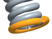
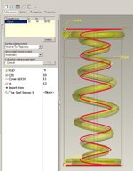
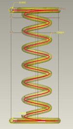
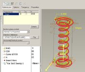
I'm trying to model a helical compression spring with a unique end feature. The helical compression spring has one closed coil as the last turn. Then I want to wrap another turn that has no pitch and just touches the last closed coil to make sort of a flange on the end of the spring. I've made a curve by equation and done a swept protrusion just to show what I'm trying to do. This equation is not right but it regenerates and gives the idea:
/* For cylindrical coordinate system, enter parametric equation
/* in terms of t (which will vary from 0 to 1) for r, theta and z
/* For example: for a circle in x-y plane, centered at origin
/* and radius = 4, the parametric equations will be:
/* r = 4
/* theta = t * 360
/* z = 0
/*-------------------------------------------------------------------
z=-1*wire_dia/2
theta=t*360
r=mean_dia/2+1.01*wire_dia*tan(theta/8)
View attachment 6391 View attachment 6392
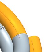
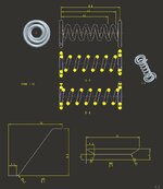
There are two problems with this equation, the added coil intersects the last turn of the spring and it leaves a small gap where it starts. Looks like I need something more like a variable section sweep where I can control the normal.
I think the last line of the equation should be :
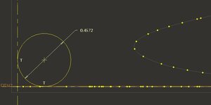
r=mean_dia/2+1.01*(wire_dia^2-(t*wire_dia)^2)^.5
The curve regens with this equation but the swept protrusion fails. This curve increases the radius much more quickly and if my math is right should fix the problem of the dead coil and the flange coil intersecting. However, the problem with the gap caused by the curve normal looks like it will be much worse.
/* For cylindrical coordinate system, enter parametric equation
/* in terms of t (which will vary from 0 to 1) for r, theta and z
/* For example: for a circle in x-y plane, centered at origin
/* and radius = 4, the parametric equations will be:
/* r = 4
/* theta = t * 360
/* z = 0
/*-------------------------------------------------------------------
z=-1*wire_dia/2
theta=t*360
r=mean_dia/2+1.01*wire_dia*tan(theta/8)
View attachment 6391 View attachment 6392
There are two problems with this equation, the added coil intersects the last turn of the spring and it leaves a small gap where it starts. Looks like I need something more like a variable section sweep where I can control the normal.
I think the last line of the equation should be :
r=mean_dia/2+1.01*(wire_dia^2-(t*wire_dia)^2)^.5
The curve regens with this equation but the swept protrusion fails. This curve increases the radius much more quickly and if my math is right should fix the problem of the dead coil and the flange coil intersecting. However, the problem with the gap caused by the curve normal looks like it will be much worse.