Continue to Site

Eng-Tips is the largest engineering community on the Internet

Intelligent Work Forums for Engineering Professionals

  • Congratulations The Obturator on being selected by the Eng-Tips community for having the most helpful posts in the forums last week. Way to Go!

Split lock ring bearing calculation 2

Status
Not open for further replies.

RH12345

Petroleum
May 30, 2017
3
Hi,

Looking for a bit of advice on a design (I've attached a couple of pictures to explain)

This is a subsea tubing hanger actuation sleeve.
sleeve_wye2pz.png


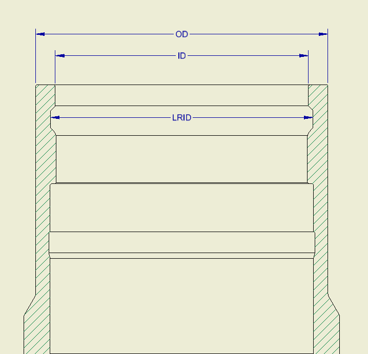
A tubing hanger retrieval tool c/w split lock ring is run into this sleeve at which point the split lock ring is energized and forced outwards into the locking ring profile. Upwards pull on the tool then pulls up this actuation sleeve.
sleeve_with_lock_ring_s2f4da.png


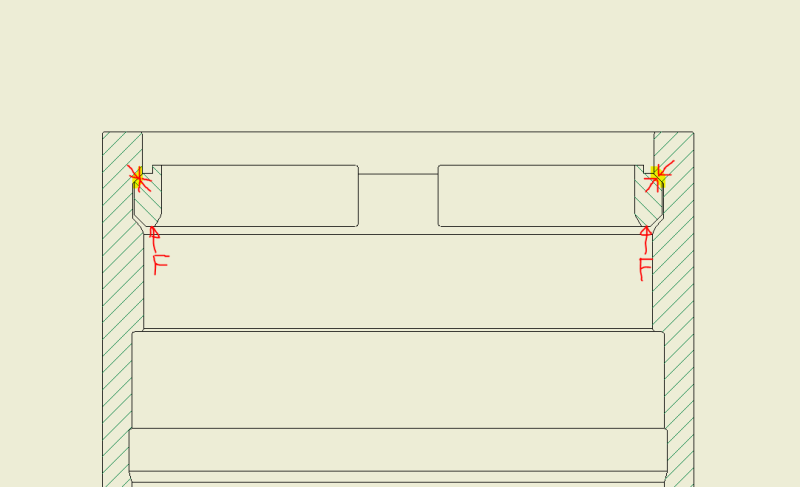
I've worked out all of the bearing & shear stresses that will arise, however the one failure mode I'm struggling with is the top of the actuation sleeve 'opening out' due to the horizontal component of the upwards force and the retrieval tool forcing its way out of the actuation ring. Something like this:
FEA_rdvpdg.png


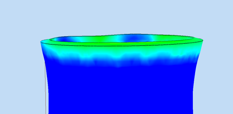
I'm not sure how to work out whether the upwards force experienced during operation would cause this type of deformation. I'm also not sure if this is a bending problem or hoop stress. If the lock ring groove was further down the actuation ring body then I would say it is a hoop stress problem but with it being so close to the free end I am not so sure so any advice is welcome.

Thanks,
RH
 
Replies continue below

Recommended for you

Yes, that deformation field looks correct, unless there is something that the outer wall can bear on (pipe wall)? I do a lot of designs using snap rings/retaining rings, and the analysis for the opening/spreading deflection like you show is important, as that deformation allows a nearby seal to extrude under pressure if the deflection is large enough. Usually I end up adding reinforcement to that open end (locally thickening the o.d.) to reduce the deflection to something tolerable. Another worry for us is wear on the contact face of ring/body after multiple cycles of installation/extraction of the ring (or actuation of the ring in your case).

" I'm also not sure if this is a bending problem or hoop stress."

It's both due to the 45 degree angle creating a wedging action, plus some shear stresses and bearing stresses at/near the contact face. Even a snap ring under the pull force "F" tends to bend/roll and create the wedging action you are working with if the force gets large enough.
 
I would say you're absolutely in danger of stretching the end of the tube and allowing the locking ring to escape- but it's not a bending problem. Hoop stress is, as far as I can see, the only way to get you there- because the tube will have to deflect around its entire diameter. You might be able to approximate by looking at a small section in bending but that won't account for localized stresses when you try to multiply that section around the full diameter.
 
i suggest you increase the thickness at that particular area of the tubing sleeve to an acceptable deformation.
regardless what type of forces is acting there, i believe there are combination of them.

R.Efendy
 
For your design, pls. check on the inner radius of the groove, that's the stress raiser together with the change in related materials thickness.
Then, for analysis, this will be imo a combination of local bearing stress which due to the inclined / oblique surface result in
hoop stress from the radial component
bending stress from the axial component
If applicable, pls. also check for fatigue strength.
Pls. check the attachment, unf. i can't upload images into the text.

Regards

Roland Heilmann
Lpz FRG
 
 http://files.engineering.com/getfile.aspx?folder=2f0fd586-480f-40a7-bffc-bd00dae49dc7&file=illu.PNG
Thanks for the comments folks, much appreciated.

I should just clarify that the picture of the FEA is exaggerated, I just did that to clearly show the type of failure I'm concerned about, but the FEA result in that picture is not an actual representation. So what I am doing now is trying to work out with an applied force of 250,000 lbf, will the end of the tube deform or not.

My design calcs have to be done using hand calcs so I won't be using FEA for this. I have found something to allow me to work out hoop and radial stresses in the actuating sleeve. This is a procedure for working out stresses for a hanger sitting on a tapered load shoulder (similar to my case):

HA_shear_1_cc7q4t.png


HA_shear_2_bgplfj.png


HA_shear_3_yskzku.png


I'd be quite happy using this on its own if the lock ring groove was lower down and not so close to the end of the pipe as bending would not really be an issue. But since it is, I think I need to do an additional bending calc to work out the bending stresses and deflection at the end of the pipe. So my question is, does anyone know how to perform such a calculation by hand? A textbook reference would be great. I had thought of simplifying this and effectively 'unrolling' the pipe into a beam and working out bending that way but that doesn't seem like a very accurate way of doing it.

btrueblood, you mentioned you have to work with this kind of design regularly.
"Usually I end up adding reinforcement to that open end (locally thickening the o.d.) to reduce the deflection to something tolerable" - how do you work out this deflection, as this might be exactly what I am trying to do...

Thanks,
RH
 
Folks,

Thought I would update as I think I have found the solution.
Roark's has a case similar to mine where a radial load is applied to a cylinder at a distance 'a' from the end. This works out deformation and angle of deflection. I think I can use this by simply using a negative value for the force as mine is acting radially outward

roarks_iryzi9.png


RH
 
I usually rely on FEA. Rolling (coning) of the ring, wedging action and bending/bell-mouthing of the end o.d. is something we have seen in hydrotesting and in FEA, but I have not seen a decent reference for a hand calc, sorry. The closest I have seen is the rotorclip guide formulas for end margin, which are useful for strength calcs but don't give you much information on distortion, see:


and

 
I agree with those who replied that extrusion and stretching at the end of the tube should be a great concern.
 
Status
Not open for further replies.

Part and Inventory Search

Sponsor