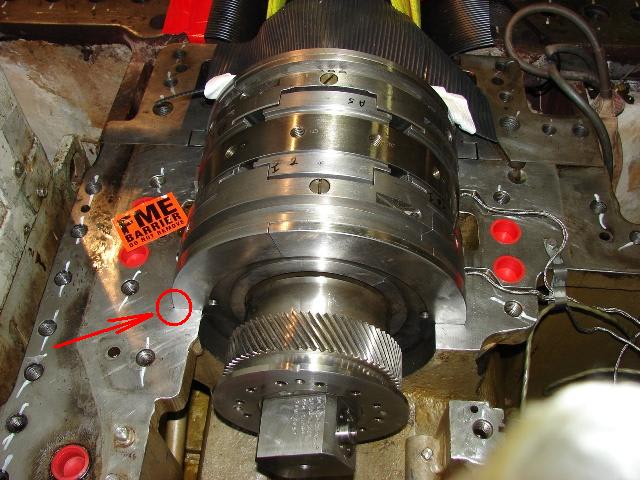
I am a machinist that is working for a plant mechanic and a turbine mechanic I am machining a bearing spacer to the dimension they have specified this is a split spacer that appears to be soldered together for final machining. the question is what is the proper or recommended way to break the solder joint? would like to know what ingersol recommends but nobody can tell me. but they expect me to split it for them. Anyone out there having done this before and could give me some insight would be appreciated.
Tek-Tips is the largest IT community on the Internet today!
Members share and learn making Tek-Tips Forums the best source of peer-reviewed technical information on the Internet!
-
Congratulations TugboatEng on being selected by the Eng-Tips community for having the most helpful posts in the forums last week. Way to Go!
Split Bearing spacer
- Thread starter smptrsn
- Start date
Similar threads
- Locked
- Question
- Locked
- Question
- Locked
- Question
- Locked
- Question