Continue to Site

Eng-Tips is the largest engineering community on the Internet

Intelligent Work Forums for Engineering Professionals

  • Congratulations cowski on being selected by the Eng-Tips community for having the most helpful posts in the forums last week. Way to Go!

Skewed Shear Walls

Status
Not open for further replies.

davidfi

Structural
Sep 28, 2005
39
I am designing a wood frame structure with non-parallel shear walls. I am trying to determine how to distribute forces to the skewed shear wall. Below is an example of what I think I can do:

On one line of resistance, I have a 10' long wall (plywood shear wall) at 0 degrees and another 10' long wall at 30 degrees. My thought is to divide the skewed wall into orthogonal components (8.66' in the 0 degree direction and 5' in the 90 degree direction). If I apply a 5000 lb load to this line of resistance, my unit shear would be v = 5000 lbs / (10' + 8.66') = 268 lbs/ft. In the skewed wall, I will have F = 268 lbs/ft x 8.66' = 2321 lbs.

And then I would analyze the structure in the orthogonal direction and come up with a similar unit shear. In the orthogonal direction, I have a 10' long wall at 90 deg and the same 10' long wall at 30 deg. If I have the same 5000 lb load, my unit shear would be v = 5000 lbs / (10' + 5') = 333 lbs/ft. In the skewed wall, I will have F = 333 lbs/ft x 5' = 1665 lbs.

Lastly, I would combine these using the 100% + 30% rule. So I would have: F = 1.0 x 2321 + 0.3 x 1665 = 2821 lbs and F = 1.0 x 1665 + 0.3 x 2321 = 2361 lbs. Using the controlling 2821 lbs in this wall, the unit shear in the skewed wall will be v = 2821 lbs / 10' = 282 lbs/ft.

Does this seem correct?

Thanks for any advice!
 
Replies continue below

Recommended for you

What's your total load? Seems that you could transfer it all into the non skewed wall and not spend time/money trying to create a different solution. Do you have a diagram? I think I understand the concept but like visuals.
 
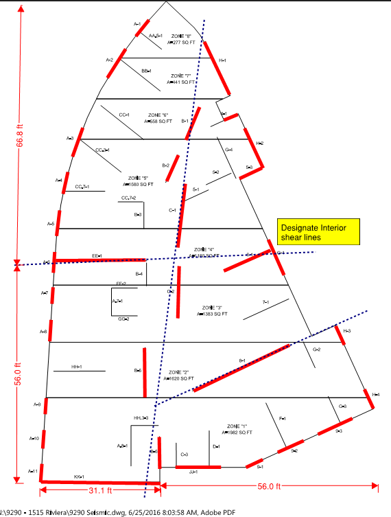
I wish I could avoid skewed walls, but I have few walls that are not skewed. Take a look at the attached PDF layout of the shearwalls. Previously, I had just done a rigid diaphragm analysis, but the plan checker says I cannot assume a rigid diaphragm because I have a Type 5 Horizontal Irregularity. He was okay with me enveloping flexible and rigid diaphragms.
 
 http://files.engineering.com/getfile.aspx?folder=0a114fda-7d7f-4dfb-8ffb-88ee57e21757&file=9290_Seismic_Model_(1).pdf
I like your rigid diaphragm assumption since it seems like there are plenty of walls and short diaphragm spans that will keep diaphragm deflecation at a minimum. Did you model it in software for the rigid diaphragm analysis? If so, I'd just model the diaphragm as semi rigid and ignore nail slip for load determination.

If that's not an option, remember that flexible diaphragms are treated as simply supported beams between lateral resisting elements. Draw out the free body diagrams and you should be able to get the forces. Are you going to provide full depth collectors at shear walls? Blocking and straps? Sub diaphragms and transfer diaphragms would be a pain with that layout.
 
I thought the rigid diaphragm was a good assumption too since I know that it will behave a lot more rigid than flexible. I did the rigid diaphragm in excel, so I do not have an option to do a semi-rigid analysis.

I guess I'll just do the flexible and envelope it.
 
For seismic, does ACSE 7 section 12.7.3 require a 3-D model for nonparallel shear walls. The force applied to the skewed wall may be higher than you think. In the second paragraph, wouldn't the 268 lbs need to be divided by cos 30° to determine the force in the skewed wall? At the same time, there will be an orthogonal reaction causing torsion that must be resisted by the lateral system in the orthogonal direction. Skewed shear walls makes my head hurt. Once the forces in the walls is calculated, the next challenge is designing and detailing the diaphragm.
 
I'd actually model the structure rather than do a simplified 'hand' distribution. You will find that the principle axes for the response don't necessarily align with the assumption that the resultant load is up and down the page as I think you have assumed.

You might get close doing what you are doing, but then again you might be miles off. One of those things you want to verify via another means to justify use of any simplifications and assumptions. If it's multiple storeys, I'd suggest modelling it is the only way.
 
When I was first looking at this, I took the 268 and divided by the cos(30) to get the resultant. But then I looked at another wall that was at 89 deg. If I apply a load at 0 deg to this wall, the component force is very small, but if I divide by cos(89), I get a huge resultant. This does not make intuitive sense. Am I missing something?

Do you have any recommendations for 3D software for wood shear walls? The only analysis software our office has is risa 2d.

Thanks!

 
I second RISA 3D. If you model in RISA Floor first, you can envelope the rigid and flexible diaphragm design.
 
My thoughts:

1) Pare down the number of designated shear walls to make the shear distribution more tractable. As others have pointed out, the collector and diaphragm design will be difficult to rationalize if you use every last wall.

2) I feel that having a simple and robust load path consisting of clearly defined and well detailed collector elements, shear walls, and connections trumps all else.

3) In my opinion, the concepts of "flexible diaphragm" and "horizontal irregularity" are incompatible. Once you go flexible, the distribution is determinate and largely unaffected by most irregularities.

4) For light frame wood structures, I find anything other than the simplest of load distribution analyses unjustifiable. I only support FEM if that method is actually faster than a flexible hand analysis. And, on occasion, it is.

I do understand that ASCE7 mandates certain things that would be in opposition to my view.

Capture19_b86noh.png


I like to debate structural engineering theory -- a lot. If I challenge you on something, know that I'm doing so because I respect your opinion enough to either change it or adopt it.
 
Status
Not open for further replies.

Part and Inventory Search

Sponsor