Continue to Site

Eng-Tips is the largest engineering community on the Internet

Intelligent Work Forums for Engineering Professionals

  • Congratulations cowski on being selected by the Eng-Tips community for having the most helpful posts in the forums last week. Way to Go!

SJI Deck to Collector Welded Connection 2

Status
Not open for further replies.

theshearstud

Structural
Jun 8, 2011
69
I would like some verification in my understanding of the welded diaphragm deck connection to a collector tube:

A) Failure limit state of diaphragm deck should be taken from the max allowable diaphragm shear values by SJI (Vulcraft Deck)
B) Connection from diaphragm deck (say, for an interior brace, your connection force would be the diaphragm shear from each side of the collector, or the "reaction" force to the brace) to a collector is governed by the AISI puddle weld shear equation.

So, assuming the same welding pattern for supports and collectors, the collector connection will provide sufficiently more resistance than the support member connection.

Is there something flawed in this logic?
 
Replies continue below

Recommended for you

I assume the tube is going on top of a beam to fill in the gap caused by the joist seats. Yes, you are correct for both A and B. The collector is basically a support, so the weld connection is the same and you can use the published diaphragm shear values. Typically, I weld the collector at each end to the support member, but there have been times when I stitch welded it to the beam below based on demand.
 
Thank for the response Mike. I guess my confusion lies in the fact that the AISI values for puddle weld capacity will normally be on the order of 1000 lb per 5/8" puddle weld....which is MUCH more than the published diaphragm shear values.
 
Though, I do agree that using the diaphragm deck shear values would be permissible and conservative. But for a diaphragm that's really grinding, I don't want to schedule 60ft of collector tube.
 
Stud said:
Is there something flawed in this logic?

I believe so. Stated in hyper logical looking computer code:

SHEAR_CAPACITY_SUPPORT = MIN(DECK_STRENGTH, WELD_STRENGTH)

SHEAR_CAPACITY_COLLECTOR = SHEAR_CAPACITY_SUPPORT

Stud said:
But for a diaphragm that's really grinding, I don't want to schedule 60ft of collector tube.

This may indeed be necessary.


I like to debate structural engineering theory -- a lot. If I challenge you on something, know that I'm doing so because I respect your opinion enough to either change it or adopt it.
 
KootK

Thanks for you input. The Vulcraft design guide directs you to AISI for this connection design (which accounts for weld strength and deck rupture). I'm assuming for a reason, if not, Vulcraft would just say to use the diaphragm design values when sizing collector tubes.

If you have 100ft long deck with allowable shear of 100 plf, and AISI gives you connection capacities of 500plf: you would theoretically only need 20ft of collector connection to take the load out. Your deck length is still 100ft and therefore you deck shears haven't changed.

I was hoping someone had come across this before since there are not many examples published.
 
Stud said:
The Vulcraft design guide directs you to AISI for this connection design (which accounts for weld strength and deck rupture). I'm assuming for a reason, if not, Vulcraft would just say to use the diaphragm design values when sizing collector tubes.

I disagree. Obviously, there are diaphragm failure modes other than just weld / base metal failure. It makes no sense to me that those other failure modes should just be disregarded at collectors for some reason. Those are often the locations of highest demand. Perhaps you can post a clip of that Vulcraft blurb for communal review.

Stud said:
Your deck length is still 100ft and therefore you deck shears haven't changed.

Again, I contest. I believe that your effective deck length is only as long as your collector unless you're doing some fancy stuff with sub-diaphragms etc.

Stud said:
and AISI gives you connection capacities of 500plf:

At this capacity, a standard 3' wide sheet of decking should be able to resist 1500 lb of shear applied at its end. Do we really believe that's plausible? That's a whole, mature Holstein cow for comparison.

Floor-Deck-Sheet_pa78h3.jpg


Holstein_heifer_tnxxc6.jpg


I like to debate structural engineering theory -- a lot. If I challenge you on something, know that I'm doing so because I respect your opinion enough to either change it or adopt it.
 
KootK

You may not be familiar with the Cold Formed Steel code, but the equations given considers deck failure modes.

Would you consider the shear stress in 36" deep beam that is welded at the bottom of its web with a 2 inch shear tab to only be concentrated in the bottom 2" of web?

The numbers I gave were obviously for demonstrational purposes.

I do agree with you that its possible that localized diaphragm shear stresses can occur, but I do think that using v_allow diaphragm values are a bit conservative. Again, why would Vulcraft refer you to AISI welded deck shear connection formulas if the correct answer is to use the diaphragm shear values.

If you need a copy of the design guide:

 
I can see the point you are trying to make, but I agree with KootK on this one. I don't read the design guide that way at all. The design guide is referring the user back to the AISI equations for connections because, they mention (in the previous sentence) that connections can be clustered but care must be taken not to overstress the deck. In that case, the published diaphragm values wouldn't be accurate.
 
OP said:
You may not be familiar with the Cold Formed Steel code, but the equations given considers deck failure modes.

I am certainly acquainted with the CFS code and have access to it. I'm no where near as familiar with it as I might like to be with, say, Liv Tyler. If you quote the specific clauses and equations that you've been referring to, I'd be happy to take a look. My suspicion is that critical deck failure modes like cross flute shear buckling are not included in the AISI weld checks.

OP said:
Would you consider the shear stress in 36" deep beam that is welded at the bottom of its web with a 2 inch shear tab to only be concentrated in the bottom 2" of web?

Of course. Right beside the tab that's what the shear stress would be and that's how one would design the welds. Regardless, this argument neglects a fundamental difference that exists between diaphragms and the wide flange beams that we're so fond of comparing them to.

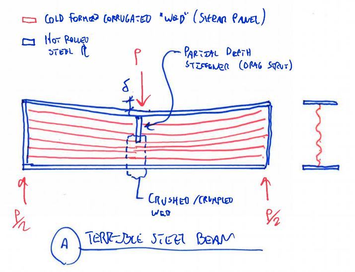
The "web" of a diaphragm in wood or bare steel deck is assumed to be a shear panel for analysis. That means that our deck elements are assumed capable of transmitting in plane shear and no other in plane forces. They can't transfer tension, compression, or in plane bending. Obviously, these assumptions are more true for some situations (cross flute tension) than they are for others (along flute compression).

The web of a steel beam is capable -- very capable -- of transmitting in plane forces other than shear. This is why it is analytically appropriate for there to be such a thing as a partial depth web stiffener at a concentrated load. If the web of a wide flange beam were actually made of a shear panel material like corrugated deck, it would clearly be quite inappropriate to have a partial depth stiffener. And so it is with big old roof decks.

OP said:
The numbers I gave were obviously for demonstrational purposes.

That wasn't obvious to me. The 500 plf seemed fairly consistent with the 1000 lb/weld that you quoted earlier. I've only got time to use what you give me.

OP said:
Again, why would Vulcraft refer you to AISI welded deck shear connection formulas if the correct answer is to use the diaphragm shear values.

I get where you're coming from but do you really want to hang your hat on your interpretation of a vague statement in a non-code document? Looked at conversely, if the AISI equations can be used for drag struts, why would't we also use them for the support cases where shear exist? Clearly, something about the discrepancy seemed fishy to you or this thread wouldn't exist. In my opinion, your innate structural intuition has steered you in the right direction here.

Vulcraft said:
Fastening can be clustered at selected shear collectors but care must be taken not to overstress the diaphragm by funneling all of the horizontal shear into or out of the system at one location. The AISI specification provides the designer with equations for calculating allowable arc spot weld stresses for shear

I agree with Mike's interpretation on this. That, essentially, being: MIN(weld capacity, deck capacity).

Capture1_ivcfe8.jpg


I like to debate structural engineering theory -- a lot. If I challenge you on something, know that I'm doing so because I respect your opinion enough to either change it or adopt it.
 
You've both made some good points that I now agree with. Thanks for the input.

I did speak with a Vulcraft Designer today and he directed me to the SJI Diaphragm Design Manual, 3rd ed for deck to collector connections. He said that SJI has equations, that should be used with the AISI connection capacity values, that will account for deck buckling ect.

I suspect the values will be less than the AISI connection capacities, but more than the allowable diaphragm shear. I have not had a chance to investigate, but I found the guide if you all are interested.


Again, thanks all for the input.
 
Status
Not open for further replies.

Part and Inventory Search

Sponsor