Continue to Site

Eng-Tips is the largest engineering community on the Internet

Intelligent Work Forums for Engineering Professionals

  • Congratulations cowski on being selected by the Eng-Tips community for having the most helpful posts in the forums last week. Way to Go!

Sistering to Existing joists calculation question 2

Status
Not open for further replies.

mfstructural

Structural
Feb 1, 2009
230
I have a design I'm working on where there are currently 2x6 ceiling joists installed that are spanning 13.5 feet on each side of a load bearing wall in a residence. The owner wants to remove the wall and replace with an LVL. The LVL will be a 3 ply 7.25" beam that will be installed with its bottom flush with the ceiling joists to have a flat ceiling. The attic above is currently unfinished, but he wants to finish it and live up there at some point, so I have to reinforce the existing joists. It's an older home but I'll be conservative and assume a No. 2 value for Fb for the existing joists. My question is regarding to designing the sister member. Assuming the members are the same strength, Fb and E, can I apply a percentage of load to each based on the ratio of their section moduli? For example if I have 100 PLF on a joist can I apply 36.5% of the load to the 2x6 and 63.5% of the load to the 2x8?

Another question is regarding the number of screws to use? I would use shear flow to calculate this correct? Because the 2x8 will be higher and the sheathing will be placed on it, it will transfer the floor load to the 2x6 via the screws fastening them together.

Lastly, what is everyone's thoughts on using face mounted hangers vs. top mounted (with the flange)? I prefer to user vertical but the contractor I met with is wanting to use face mounted.

Thanks
 
Replies continue below

Recommended for you

1. The load distribution is based on the EI ratio as the joists must deflect the same. Then you can go back and figure the load each member takes to get the common deflection.

2. Just put in enough screws to transfer the load the 2x6 will take in shear.

3. Face mounted are fine, and simplest to install.

Mike McCann, PE, SE (WA, HI)


can I apply a percentage of load to each based on the ratio of their section moduli?
No - not the section moduli....rather what Mike states above - the relative EI values of each member. Section moduli (Sx) are used to derive stress, not stiffness.
For a 2x6 and a 2x8 of the same E values, it would be 30.4% and 69.6% respectively.

 
mfstructural said:
I would use shear flow to calculate this correct?

In theory, you're absolutely right, the forces on your fasteners would be the vector sums of:

1) The vertical shear transfer required to shift the load out to the 2x6 and;

2) A little bit of horizontal shear transfer (VQ/IT) required to force your non-centroidally aligned pieces to act as a composite unit.

For this situation, because your member centroids will be very close to aligned, #1 will dominate and I'd ignore #2 as the other gentlemen have recommended. I just wanted to point out that your instincts about shear flow here were not wrong, and I think that's important.

With these sistering situations, you also need to consider how much load / deformation is locked into the system when the sister is added. If that amount is appreciable, and jacking will not be performed to relieve, then dividing the load out based on Ix values is not technically correct. Here, because the ceiling joists are probably starting off with very little load, you're probably fine ignoring this effect.
 
I did a similar project not that long ago. The idea was to sister a LVL to a existing wood beam to carry some additional load. The decision making process we went through on that project may help you with your process.

Analysis Method #1 was exactly as Msquared suggests. The load was distributed to the two members based on relative stiffness. Make sure we connect the two members together along their length so that they act as one. The problem was that the LVL was so much stiffer, that it took up too much of the load and would fail its stress check. By less than 10%, but still.

I suggested to the EOR that we use a larger LVL and explained why. He suggested the method below.

Analysis Method #2: Calculate the capacity of the LVL and the capacity of the existing joist and add them together. If the total was sufficient, then the design was okay. Provided, of course, that these sistered members were sufficiently connected together along their length. I believe we used nails though instead of screws.

Now, there were some significant caveats to our use of method #2:
a) The EOR had worked on a number of very similar projects over the last 20 years and felt comfortable that the concept was sound based on the outcome of these project.
b) The fact that the LVL (via method #1) was only a little overstressed.
c) None of the connections from joist to girder could be overstressed.

The justification the EOR gave me was that the failure method of this would beam would be sufficiently ductile that once the LVL started to fail, the extra load would go into the other beam before we would have any true failure. Since he was the EOR, we went with his perferred method #2.... Though I still very much respected his decision.

This isn't meant to tell you to use MSquared's method#1 or my EOR's method #2. They both have their merits. I just point the decision making process because I think it demonstrates very well how two good engineers can justify fairly different design decisions.
 
Anybody who thinks that a wood flexural failure is ductile ought to do some rooting around on Youtube. More like explosive.
 
KootK -

I'll admit that I hadn't looked at any wood failure videos at the time. Thanks for pointing that out! Makes me feel better about my preference for method #1. That being said, I'd still argue that the EOR's method #2 is not so egregious. Though maybe I'm not as confident in that statement as I would have been yesterday.

Wood beams certainly don't exhibit the type of load re-distribution that steel does as its extreme fibers get overstressed. It's not that level of ductility. Maybe ductility isn't the proper word. Maybe "sufficiently inelastic to share load between the two members" would be a better term.

Now, if I were really concerned about the subject, I might return to the project files to see exactly how much load was existing, put that into the existing beam, then split the superimposed dead load and live load between the new and existing based on EI. See if that negated the 10% overstress in the new LVL (which was based on load sharing the entire load).
 
Comparatively speaking, wood exhibits ductile behavior to an extent, and as long as the sisters are standing shoulder to shoulder, the load sharing takes place in a much earlier stage before stressed to extreme. Thus method 2 makes sense too.
 
This was the last thread where I argued the non-ductility of wood in bending: Link. Some of the exploding wood videos are linked near the end.

Someplace in that thread, I noted that failures where some degree of fracture took place before engaging an imperfection (knot etc) actually were ductile for a time. A persuasive engineer might argue that an LVL bending failure should be more ductile than a solid sawn bending failure because the very different, reconstituted character of LVL eliminates a lot of imperfections.
 
The u-tube link, Link

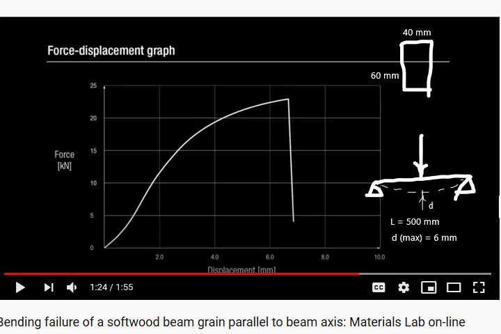
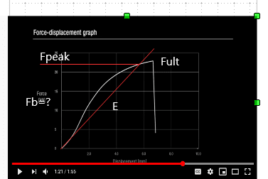
From the test setup below, I back checked the Young's Modulus of the wood specimen, the result is E = 2x10⁶ psi, which is at the higher end of the usual range 1.2x10⁶ - 2.0x10⁶. IMO, the failure performance of the specimen can still be seen as ductile until rupture. (P = 23 kN, Fb = 17.4 ksi)

e_mockij.png
 
I disagree quite strongly retired13:

1) There just isn't anything ductile looking about that graph. Quite the opposite.

2) A higher modulus only means that the piece in question would attract load, and fracture, that much more quickly within the assembly.
 
Retired13 -

Yes, that was for the beam without any growth defects, I believe. I watched the same videos. Great series of videos (from Europe, I think).

That being said, KootK's argument is a lot stronger for the video of a glu-lam failure and the video of a beam with a knot / growth defect. Very sudden failures in those cases. Pretty elastic up until failure in some cases. Maybe it looks better if the knot were not at mid span, etc.

I would still argue that Method 2 is not an egregious method. That's not a ringing endorsement from me anymore. If I were to re-do this project today, I would probably give the EOR more push back on the subject. Ultimately, it's still his decision and this guy is one of the best engineers I know. Therefore, I'd still accept it if he told me to use that method.

Note: I gave KootK a star because I think I genuinely learned something from his response. Wood tensile failures don't appear to be nearly as ductile as I had assumed. Or, at least I can't necessarily count on them being ductile failures.

 
I just add the resulting bending stress near failure/rupture. I don't know the allowable stress of wood, but guess it would be much lower than that calculated. Then look at the P/Δ diagram, the smooth curve indicates linear elastic behavior to a certain point, then change to non-linear plastic until sudden failure. So, I believe, wood beam is considered a ductile element within the (code) specified stress range.

[ADD] Also note the large deflection, Δ/L = 6/500 = 0.012, Δ = L/83, wow.
 
In didn't think about defects in comparison. Wasn't wood been inspected and graded for structural use? Any material with defects would have a lower ultimate strength, doesn't it?
 
JP said:
Ultimately, it's still his decision and this guy is one of the best engineers I know.

One of the best engineers I know got ten years into his career before learning that rebar hooks don't develop bars instantaneously at the hook. Everybody's got holes in their game and being a "good engineer" is about much more than the technical minutia.
 
I think wood designer can point out the maximum allowable bending stress on the diagram.

ee_zx15zd.png


The maximum allowable fiber stress of selected structural, for beams and stringers, arranged from 1000 psi to 1500 psi. Very low in the diagram.
 
We had to make popsicle stick truss bridges in first year university. Then we smashed them all using the laboratory’s ram. The winner was the bridge with highest strength to weight ratio.

The good ones had members snap. There was a bit of creaking and groaning as wood fibres began to yield, but it was otherwise quite sudden failure.


As for screws, I would put in more than the calculated shear force. It’s hard to accurately calculate how much load goes into the new joist, and there’s little benefit in skimping on fasteners. I’d put in enough to fail the joist.


[quote R13]Comparatively speaking, wood exhibits ductile behavior to an extent, and as long as the sisters are standing shoulder to shoulder, the load sharing takes place in a much earlier stage before stressed to extreme. Thus method 2 makes sense too. [/quote]

The following is an example to back up the claim in bold on above statement.

Given a 2x6 (bxd1) that has a capacity for the load of 1 kip (P1). On renovation, the load demand increased to 3 kips, find the required sister beam depth (d2), assume b = 2".

1. Method 1 - Stiffness Method
- The capacity demand for the sister beam, P2 = 3-1 = 2 kips.
- By consistent displacement, I2 = I1*(P2/P1) = 2I1.
- I1/(I1+I2) = 1/(1+2) = 1/3 ---> I2 = 2I1---> d23 = 2d13---> d2 = 3√(2*63) = 7.6"

2. Method 2 - Capacity Method
- Since P2 = 2P1, M2 = 2M1; M1/S1 = Fb = M2/S2 ---> M1/d12 = Fb = 2M1/d22 ---> 2M1d12 = M1d22 ---> d2 = √(2d12) = ---> √(2*36) = 8.5" > 7.6" using Method 1 ---> Method 2 is err on the safe side.
 
Great discussion here. I am going to run both and see. I think since these are ceiling joists that will potentially be used as floor joists one day for a bedroom, the load will not be that high. If I were sistering to a beam, it would make me a lot more nervous.

Another question I have is related to the LVL design. I didn't want to start an entirely new thread so thought I'd ask it here. The design is going to have the LVL flush with the bottom of the joists like I mentioned in the O.P.. There are several openings they want to make and have the ceiling open. the contractor wants to install one long LVL (18' long). The opening is 115", then there is a closet which the beam will sit on, and then span the opening over the entrance which is 32 inches.

When I run numbers on a s.s. beam for the 115" span they show I need 3 plies of 7.25" LVL (they don't want to go taller than that with LVL since the joists will be 2x8s). By increasing the E to 2.0 and Fb to 2850, I can get the beam to work. The interaction ratio is 1.0 for bending. The deflection is my concern then. Since the beam is not simply supported in reality...it's a 115" span with the second span partially over a closet (bearing for 48") and partially spanning an opening (approximately 32"). Because of this my thought is that the deflection in reality is not really 5wl/384EI, but could be 1wl/185EI because it more resembles a two span beam with one span loaded...I know it's a gray area and judgement, but I'm trying to get a 2 ply beam to work.

The last question is that I called around some lumber yards to just see if they have 2.0E LVLs and what the bending strength is. When I asked bending strength they all said they don't know they just know the E. So many lumber yards have LVLs with 2.0E, but how can you be sure what the Fb is? I got the feeling when I spec out a 2850 how do I know that's what the Fb really is? I know Fb can be 2850, 2900, or 3100 for 2.0E? If I specified Fb = 3100 the 2 ply beam would work for sure.

The last thing is that the attic above has a gable roof so there won't be any load near the two long walls of the residence as there is no head room. For purposes of design, I don't think you'll ever have 40 psf there, especially if they building a knee wall and wall it off.

I included a picture for reference
 
 https://files.engineering.com/getfile.aspx?folder=c44b6c5f-77ec-45db-9ed5-fdc252b529c4&file=LVL_sketch.jpg
Folks, so that I can perhaps learn something too, are we perhaps misinterpreting one justification for Method #2 (summing capacities)? While wood does fail in a very sudden manner at ultimate strength, it does often exhibit significant creep under long term loading. Did the EOR who proposed Method #2 perhaps intend that wood creep would result in a distribution different (and more equal between members) than a simple comparison between elastic stiffnesses? Also, on this train of thought, what's the relative propensity to creep between engineered wood (LVL, PSL, etc) and the solid sawn variety?

Edit: I should stop thinking out loud... I found this APA paper: Link which states:
There is strong evidence that the LVL products (5 out of 7 products evaluated in this study) manufactured with today’s technology have a similar creep and creep rupture behaviour as solid-sawn lumber. In fact, there has not been a single instance, as far as APA is aware, when an LVL product failed to meet ASTM D 6815 requirements in the last 10 years. Therefore, an opportunity exists for standardizing the creep and creep rupture factors for LVL products without the expensive and time-consuming long-term tests, provided that the LVL product is manufactured with an adhesive, wood species, and manufacturing parameters typical of those evaluated. On the other hand, the newer generation of SCL products, such as LSL and OSL, tends to be more innovative than LVL in the use of adhesive binder systems, wood species, strand geometry, and other manufacturing parameters. Therefore, more long-term test data are needed for LSL and OSL to gain the same confidence as the LVL products on their creep and creep rupture behaviour.

So that seems to debunk a potential for differential creep to play a role in load distribution. It seems that a solid sawn and LVL beam sistered together will creep proportionally to their EI values, which will maintain the load distribution based on stiffness. I suppose that the only way that this would change would be if one got lucky, and had overload in a clear portion of a beam, such that the wood began to fail in crushing rather than the more common flexural failure modes (which all seem brittle). Needless to say that "being lucky" isn't a generally accepted engineering practice.
 
Status
Not open for further replies.

Part and Inventory Search

Sponsor