Continue to Site

Eng-Tips is the largest engineering community on the Internet

Intelligent Work Forums for Engineering Professionals

  • Congratulations KootK on being selected by the Eng-Tips community for having the most helpful posts in the forums last week. Way to Go!

Simple reinforced I-beam with angle or flatbar 1

Status
Not open for further replies.

Vonkrumm

Aerospace
Feb 12, 2020
5
Hi Guys,
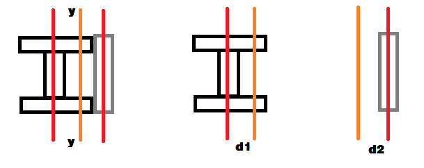
Just wondering how to work out the bending of a beam, that is reinforced with a flat-bar?

Or any piece of material for that matter (angle, C-section, ect.)

Example:
If you had a standard I-beam 30mm high, that had a piece of flatbar stuck to it's side - 30mm high (fixed to top and bottom of I-beam), how do you work out the moment of the area cross section?

Can you assume that the new area is simply the addition of the beam and flatbar areas?

(This is assuming that the flat-bar is fixed quite well to the I-beam.)

I know there are composite beams (and their associated calculation methods), but in my example above both materials are exactly the same....

Any help is much appreciated, and nice to join the forums!!!

 
Replies continue below

Recommended for you

The general method is to integrate the area times the distance from some plane. If the neutral planes of all the pieces are coincident with the selected plane then one can add their individual moments of inertia. This is a special case, it is also a common case. If they are not look up the parallel axis theorem.
 
Thanks for your response!

What's the 'selected' plane?

In the case of above:
The I-beam and the flat bar have planes that are parallel, but for them to be coincident they would have to be superimposed on-top of one another (not possible)...?
 
Any plane you like. Usually it is through the neutral plane, one of the planes of mirror symmetry, either vertical or horizontal. If the web of the I-beam is vertical then the usual choice is the horizontal plane which corresponds to the maximum moment of inertia for usual structural I-beams.
 
If I understand your question right-
Assuming the web of the I-beam is vertical,
Assuming the flat bar is vertical and centered vertically,
Then you just add the moments of inertia of each one in the vertical plane.
In the horizontal plane, you calculate a composite centroid and use the parallel axis method to find composite moment of inertia.
In the first case, the shear center will be shifted away from the center of the I-beam, which may produce unanticipated torsion in the bar when it is loaded.

For the "stuck" part- if these are physically welded, watch out for weld distortion. If glued, check shearing stress at the joint.
 
surely it's "just" re-calc the section properties of two pieces (the I-beam and the plate), using as suggested the parallel axis theorem.

another day in paradise, or is paradise one day closer ?
 
I don't think it's a shear center problem, the load is just simple bending (not offset).

So using the parallel axis theorem, do I find the new centroid, then calculate the moment of inertia of each section, about this new centroidal axis?

 
I'm a structural engineer and opened this forum by chance. I saw this question which is related to one of the very basic concepts in civil engg. I'm assuming you are interested in bending capacity about the major axis only and thus, following discussion pertains to the major axis properties only.

Assuming there will be no buckling of the cross section, there could be two types of bending capacities which you may be interested in.
1. Elastic moment capacity, My = Fy Sx
2. Plastic moment capacity, Mp = Fy Zx
where,
Fy is yield strength of the material.
Sx is the elastic section modulus = I/c ; I is the moment of inertia and c is the distance from centroid to extreme top/bottom fiber.
Zx is the plastic section modulus = Ac yc + At yt; Ac is the area of compression zone, At is the area of tension zone; yc and yt are the distance from plastic neutral axis to centroid of compression and tension zone respectively. For a symmetric shape, plastic neutral axis and centroid are the same. For an unsymmetric shape, you can find plastic NA by setting "Compression force = Tension force"

OP said:
Can you assume that the new area is simply the addition of the beam and flatbar areas?

Yes, gross area is simply the additive of nth number of areas, but whether moment of inertias are additive or not depends on where the added shape is placed.
For example, if you add a plate such that the vertical distance between centroid of the plate and section is zero, then their moment of inertia are also additive.
If, for example, you add a plate such that the vertical distance between centorid of plate and section is not zero, then their moment of inertia are not additive and the gross moment of inertia is calculated using parallel axis theorem.

I'll be glad to answer any other question related to this topic. Hope this helped.


Euphoria is when you learn something new.
 
so is the following correct:
centroid_btieu6.png


New centroid axis is y-y.

To calculate bending about y-y,

Sum the following two moments about the new axis:
Ibeam + A x d12
+
Iplate + A x d22
 
Sum the following two moments about the new axis:
Ibeam + A x d12
+
Iplate + A x d22

Yes, this will give you total moment of inertia about the new centroidal y-y axis.

Euphoria is when you learn something new.
 
but note that the extreme fiber distance has also changed.

and just so as we're on the same page …
y_NA = A_plate*y_plate/(A_beam+A_plate)

on your sketch y_plate = d2+y

another day in paradise, or is paradise one day closer ?
 
Parallel Axis theorem is a lot of book-keeping. You can also check your area moment of inertial in AutoCAD using massprop command.
 
Status
Not open for further replies.

Part and Inventory Search

Sponsor