Continue to Site

Eng-Tips is the largest engineering community on the Internet

Intelligent Work Forums for Engineering Professionals

  • Congratulations waross on being selected by the Eng-Tips community for having the most helpful posts in the forums last week. Way to Go!

Should not use piping loads (API 660 Table 2) applying to UG-44 (b) 1

Status
Not open for further replies.

mechengineer

Mechanical
Apr 19, 2001
268
Currently whatever from client or vendors, all of them use the nozzle external load applying to UG-44 (b).
I think that should not use piping loads (API 660 Table 2 or client specification for nozzle external loads) applying to UG-44 (b)
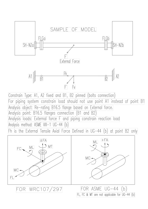
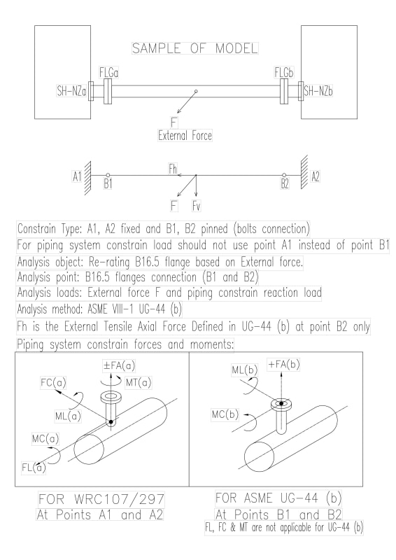
Piping Loads Apply for Local Stresses Analysis (WRC107/297) and the External Loads on Flange Apply for Re-rating Flange of B16.5 [(UG-44 (b)].
1. The analysis points are different. One is the nozzle neck to shell interface, and another is the sealing joint of a pair of flanges.
2. The loads are different. One is Piping Loads. That is the constrain loads at the point of the nozzle neck to shell interface, which derive from internal pressure, thermal load and boundary constraints on the integrated piping system by Caesar II analysis. The piping loads is applicable for WRC107/297 for local stresses analysis
Another is the External Loads on Flange EXCEPT piping loads derived from internal pressure, thermal load (as we know that the internal pressure and temperature have been already considered in the flange of B16.5). It is applicable for UG-44 (b).
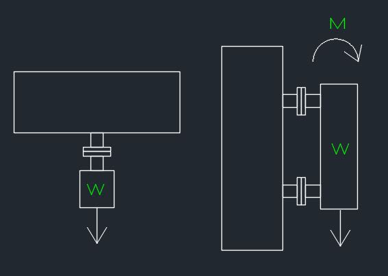
The below sketch may help to understand the external load on nozzle flange.
'W' shall be considered as the external force for the nozzle flange.
'M' shell be considered as the external moment sue to W for the nozzle flange.
3. Solution is that the case need to use UG-44 (b) is rare and most of design may not require UG-44 (b).
UG-44_iago6r.jpg
 
Replies continue below

Recommended for you

It is true that the load application point may be different. But a load is a load is a load.

Your contention that the forces and moments from a piping analysis somehow are applied to the nozzle-to-shell junction, and yet somehow do NOT pass through the intermediate flange is confusing, at best.

UG-44(b) is a mandatory part of the Code (albeit the language is a little confusing insofar as the use of the word "may"). It is mandatory to check whether the combination of internal pressure and external load on pressure vessel flanges that connect to external piping will be excessive in the context of the failure mode of "leakage". The methodology in UG-44(b) is one such method. U-2(g) opens it up to other options: I would recommend ASME Section III, Division 1, Subsection NCD, NCD-3658.3, using Service Level A Service Limits; EN-1591-1; or another method acceptable to the inspector.

The API 660 loads do result in needing to up-rate flanges: I have a spreadsheet running all of the possible combinations.

But reducing the piping loads is always an option.
 
Can. Worms :)

The problem with sloppy work is that the supply FAR EXCEEDS the demand
 
@TGS4,
Thanks for the comment. I correct and clarify my thinking as below. UG-44 (b) loads shall include the external forces/moments and the conetrian loads.

UG-44_b_dvffqt.jpg
 
Other than clarifying that the two locations are slightly different (which was already granted), your post doesn't demonstrate why loads from attached piping would be applicable for nozzle stress calculations and not for flange leakage.
 
@TGS4,
My original post said the piping loads (from API660 table 2 or client specifications) that is not applicable for re-rating B16.5 flange. But I corrected and clarified it with my post at 16 Jul 22 08:10.
Analysis object: Re-rating B16.5 flanges as per UG-44 (b)
Analysis loads: External force 'Fh' and piping constraint loads at the flange joint (B1 and B2).
Force +F(b), ML(b) and MC(b) to be considered as piping constraint loads to re-rate B16.5 flanges. But +F(b), ML(b) and Mc(b) are totally different with +F(a), ML(a) and MC (a)because the constraint type is different. The constraint loads at points B1 & B2 should be less than point A1 & A2 due to 'soft' constraint (bolts connection). Therefore it should not use the nzzle external loads at point A from API 660 Table 2 (or client specifications)for UG-44 (b).
UG-44_t6iesv.jpg
 
The flanges are not pinned joints, they are moment resisting, with typically less flexibility than the moment resisting connection at the vessel.
 
If you claim that the API 660 loads are not applicable at the flanges, then what loads would you use? Would the loads be lower or higher? And what's your justification for your response?
 
@TGS4,
By using Caeser II to obtain the actual constraint force/moments at points B1 & B2 (flanges joints) to be provided by EPC or owner.
Or as manufacturers they may provide the limit for the external axis tensile force and bending moment according to the difference of MAWP and design pressure of the nozzle flange to client (user or EPC).
Regards.
 
@mechengineer - on this point, I am in complete agreement with you. However, the schedules of projects often do not support this. And there is an infinite set of combinations of axial forces and bending moments, so I am loathe to put the responsibility to the manufacturers to develop/calculate limits.
 
Most fabricators would happily decline such an opportunity :)

The problem with sloppy work is that the supply FAR EXCEEDS the demand
 
@TGS4,
Appreciate your understanding, but it would not help to manufacturers.
As manufacturers, to avoid taking time to dispute with EPC to obtain the actual nozzle loads (of cause it is for the case that the Nozzle Load Table failed to apply), the only way is to provide the limit of nozzle loads so that may be able to take the possitive action to control the project schedule. This is what I am doing in my current projects.
The problem is pressure vessel design taking out from EPC to a manufacturer. So EPC just considers that the design shall be easy for piping to give the Maximum Loads Table for piping layout. They don’t care what will happen in PV manufacturer side for those loads. In China government companies, I worked 25 years ago, it was not like this, PV design was EPC responsibility, and a project would not delay due to nozzle loads and nozzles locating from piping or equipment design.
As for PV fabrication, girth flanges, forming head, re-pad, saddle support, manway with davit ... ... except nozzle pipe and skirt, all are purchase parts as per national standards parts manual. The PV manufacturer just purchase all components and weld together. It was quite efficient work. I remember that 90% components in drawings BOM are 'standards' parts. Now I have worked in Singapore for more than 20 years. What I have seen is that the manufacturer almost has to fabrication all components of the pressure vessel except the flanges and bolts.
It was only the national codes to follow and no company’s specification/standards drawings to be followed in that time in China. Till now I have not understand that so many companies specifications, what is the point to make it a bit difference. For example saddle supports, Shell, Chevron, Total ... the dimensions all are different if the company specification different. The manufacturer almost has to fabricate all components of the pressure vessel except the flanges and bolts.
Sorry that I may talk too much, just share what my feelings and working experience in pressure vessel design and fabrication.
Best Regards,
 
TGS4 - Was UG-44b introduced in 2019 code & then revised in 2021 code? I'm not seeing much difference between 2019 & 2021 on it.

Tolerance is the virtue of the man without convictions -GK Chesterton
 
It was introduced in 2019 and not modified in 2021. We are trying to get some modifications for the 2023 Edition.
 
Status
Not open for further replies.

Part and Inventory Search

Sponsor