Warross said:
How do we find an easy way for engineers, technicians and electricians to match switchgear clearing ratings with transformers offset currents.
The answer is the Available Short Circuit Current. (ASCC)
This is easily determined by dividing the transformer rated current by the %Impedance of the transformer.
The interrupting ratings of breakers and switchgear are ASCC values.
This needs only simple math.
Two things I'm thinking about:
1) I've heard of single phase to neutral short circuit values at or very near the transformer exceeding L-L-L short circuit values by as much as 125%.
Is there any truth to this? How or why does it happen?
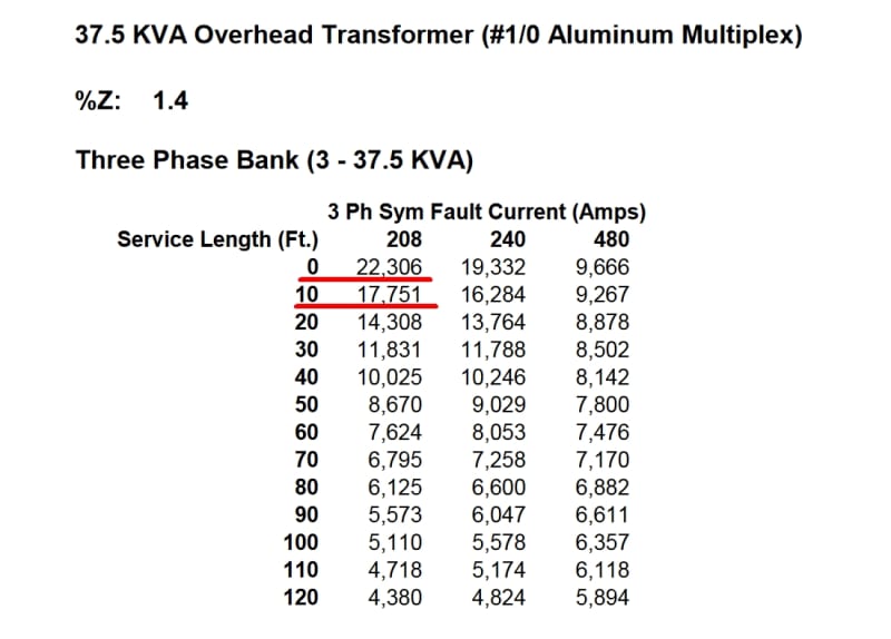
2) I'd like to include the conductors between the transformer and main disconnect when determining the AIC value of service equipment for NEC 110.9 and 110.24... For example, based on transformer impedance alone I'm over 22kaic, however if I include 10 feet of service drop I dip below 22,000 amps:
22kaic vs 65kaic is money saved, legally allowed by the code. (Think of it like taking advantage of motor wire sizing rules, where I can save copper, material and labor by using 430.25 and 440.35 to its advantage)
Divide the transformer rated current by the %Imp and compare with the interupting rating printed on the circuit breaker.
What about the offset current?
When a breaker with a 10,000 Amps interrupting rating is tested, it is tested at the current that would result from an offset current at a typical transformer X:R ratio.
Correct if I'm wrong, but is it something like an X/R of 20? Or am I wrong thinking of something else?
If you are working with low impedance transformers, it may be well to google interrupting ratings, testing and ASCC.
When a transformer X:R rating is above the test X:R, it may need higher rated switchgear.
I don't remember the specific X:R ratio.If I have to spec a low %Imp transformer I will refresh my memory.
So, the easy way is to use simple arithmetic and leave the hard math to the testers.
I understand, but what about an electrician at the supply house doing a commercial service change? Going by own preconceived notions (which as a disclaimer could be very wrong), molded case breakers assume an X/R so serve it is not likely to ever be encountered in the real world.
A suggestion:
Under short circuit conditions most of the resistance will be in the branch circuit.
Assume rated voltage applied to the branch circuit.
Understood, but I'd like to include the whole picture including the service transformer, drop, and feeder. This IMO gives the best results, even if the actual value is off by 10%.
If I'm right, table 9 assumes a 75*C conductor temp for R, so, in theory, the final number will always be lower than the actual value. Which is good for disconnection times.
As is it was UL determined that a short circuit value 125% and over of a breaker's magnetic trip threshold reduced the incident energy at a short circuit to the degree that it meets the requirements of parallel arc fault protection.
Breakers typically trip instantaneously at 10 times their rating, using a figure of 15 times (or your choice) will allow a safety margin and allow for some voltage drop in the feeders.
I'm confused. Is voltage drop really important during a fault condition?
I mean yes the circuit becomes a voltage divider, where about 1/2 the normal line voltage is seen on the faulted object relative to remote earth.
It is for this reason why I am concerned about disconnection times, as values and duration exceeding the IEC's body graph can do harm to the human body.
Wiki said:
Log-log graph of the effect of alternating current I of duration T passing from left hand to feet as defined in IEC publication 60479-1.[21]
AC-1: imperceptible
AC-2: perceptible but no muscle reaction
AC-3: muscle contraction with reversible effects
AC-4: possible irreversible effects
AC-4.1: up to 5% probability of ventricular fibrillation
AC-4.2: 5-50% probability of fibrillation
AC-4.3: over 50% probability of fibrillation
For each size breaker, list the maximum circuit impedance based on 120 Volts.
eg: 20 Amp breaker, use a minimum of 300 Amps.
120V / 300A = 0.4 Ohms maximum circuit resistance for a 20 Amp breaker at 120 Volts.
Very doable! Good idea, thank you!
FWIW, this is why I want to reduce the POCO trafo to an R value.
For 240 Volts, circuit resistance may be doubled.
You then may use two tables:
1. Maximum Ohms circuit resistance for a given breaker rating.
2. Ohms per 100 feet of the wire sizes under consideration.
This will allow the electricians to determine when a larger wire size is needed and to select the appropriate size.
For number two- I want to take the whole system into consideration. At least that is how its done in BS7671...
Consider a ball field lighting application behind a school or college. There may be a 60, 125, 225 or 400 amp feeder going for some distance to a food service hut before the final branch circuit leaves that. Or a farm house to a work shop going beyond. Or a 60 amp life safety feeder going up 10 stories to a pent house panel in a plus sized building... yes I've seen prints asking for #6 on that one... no-no in my book.
Total Z I think is key.
Zs=Ze+(R1+R2)
")