Tek-Tips is the largest IT community on the Internet today!

Members share and learn making Tek-Tips Forums the best source of peer-reviewed technical information on the Internet!

  • Congratulations TugboatEng on being selected by the Eng-Tips community for having the most helpful posts in the forums last week. Way to Go!

Shed Dormer on House w/ Exist Gable Dormer

Matt PE

Structural
Joined
Jun 6, 2023
Messages
23
Location
US
I have a client that wants to put a shed dormer on the rear of an existing 2.5 story brick house to convert the attic into living space. Dormer is to run the entire length of the building (21 feet). Plan is to cut out the rear of the roof, anchor a sill to the existing brick, install a 2x6 wall ~ 5 ft tall atop the brick, and then add the new 2x12 rafters at 3:12 slope.

There will be a ceiling joist, but I'm not convinced it is low enough to be effective. I would prefer a structural ridge here. Drop in an LVL ridge beam; everyone sleeps at night. Client is OK with this and actually prefers a structural ridge for the same reason.

Here's the twist:

There is an existing gable dormer on the front of the house.

In my opinion, the existing valley rafters and cross ridge are structural members, i.e. the reactions need full support. That brings a point load in dead center of my proposed structural ridge.

I can get a reasonable size LVL to take the point load if the rest of the roof around it is "conventionally" framed. (Existing ridge is a rough cut timber; 100 year old house.)

If there were no point load, I can get a reasonable size LVL as a structural ridge to carry the uniform load coming from the front portion of the roof, which I now think I need to carry.

The point load on top of the uniform load kills the beam and pushes me to a very deep LVL or even steel, which is not feasible here.

Thoughts?

Has any one run into this situation?
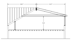
Screenshot 2025-07-02 181346.png
 
1) Use structural screws instead of bolts
2) They can probably cut a hole in the gable end and fish it up that way.
I'll consider screws.

It's a row house on a city block. Common walls. Can't cut through the gable.
 
Might be easier to shore up the roof, cut out the ridge and drop the new ridge in with a crane.
 
I am trying to picture the original load paths since you will be altering that by any modification.
Does the right side currently have a stiffleg near the brick wall like the left side? Is the stiffleg isolated to the hip rafter or is it part of a kneewall?
What do you know about the floor framing under the stiffleg? Is there a load carrying beam there?
I assume the right side has rafter framing on the same pitch as the left side.
Is there a ceiling joist or tie at the top of the brick walls or at the top of the stifflegs currently?

Thought: Leave the original ridge and install 2 beams (or more) offset a little from the ridge. Cross fasten them to each other laterally. Install them as LVLs so you can bring in the layers and attach them together in place? I am trying to not cut the building in half to replace the ridge configuration and keep the point load mags down. I am scared of those "highly ductile" 100 year old brick walls.😊
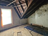
Sorry, that's not a stiffleg on the left in the original. Proposed partition wall to finish off the new room. Photo of existing valley rafter where it meets existing brick wall attached.
 

Attachments

  • 20231010_105657.jpg
    20231010_105657.jpg
    2.3 MB · Views: 15
Might be easier to shore up the roof, cut out the ridge and drop the new ridge in with a crane.
It's a constructability issue.

If I had room, I would have just gone with the quad 18" LVL on PSL columns awhile ago. Rent a crane for half a day.

This is on a dense city block. A crane would require a street closure, which the City won't give us. Needs to be carried up 3 flights of stairs and installed by hand.
Ugh, are they gonna be able to get the ridge up thru the stairs?
 
I guess in theory you could design a steel truss with bolted connections.

Anything is possible at a cost
 
I assume the window in the picture is the 33' wall in your drawing and that the right roof slope in the picture is the front existing gable. Looks like 2 different roof slopes in the picture.

I realize by design the ridge board is not generally a structural member, but in this case, parts of it are functioning as one. No doubt the valley rafter is a loaded beam. You need to assume all of it is functioning as a tension/compression member. Beams have no idea why they are present, and they serve whatever deformation they can resist. I have been the one to actually cut a lot of wood beams years ago and the older the building, the more I realized this. Many times, my saw blade kept binding as I cut. The beam was resisting compression (not by design) and kept closing my sawblade gap as I cut. After multiple restarts of cutting, I finally got through. At the end of cutting, my sawblade cut in areas was thinner than my sawblade. What was worse, was beams in tension (not by design). I would get "almost through" the material without it binding any, and near the end the remaining material would snap in half at once. I look and where my 1/8" saw blade was, there is now a wider gap than my sawblade (3/8" to 5/8" at times). There were many times nothing happened, but you remember the ones that do.

With the presence of multi-wythe brick, I highly advise you to "discretely document " the cracks, plumbness and measurement of the brick walls in multiple locations before ANY demo. I mean highly document with digital pics and accurate measurements. Discrete because laymen are not capable of understanding any change that does occur whereas engineers can. Less headaches when assessing what may have moved if you do not have to deal with peoples fears and emotion.
Good advice and that's kind of where I am going with this.

I think the existing roof is somewhat functioning as a "teepee" with the two valley rafters in the front and one (likely more) of the common rafters on the back acting compositely as the third leg. So although technically flexural members, they are taking compression too (your experience with the binding saw blade.)

Between that, and I think the old timber is MUCH stronger than we give it credit for (at lest much stronger than I would assume for analysis) the roof is still standing. The existing ridge board is probably acting as a ridge beam somewhat, and the loads aren't quite as high as I'm assuming because of the support provided by the other rafters as described above.

I'm obviously interrupting this behavior.

A little background: the owner came to me with stamped (!) drawings prepared by another engineer that is no longer around. The drawings I was given show sandwiching the existing ridge board with 2x12s to create a ridge beam. My assessment was that that was not heavy enough because you not only have the uniform load coming from areas of the roof are not tied across, and thus require support, but the valley rafters are putting a point load on it as well.

Wanted a sanity check before causing this guy a lot of heartburn with a heavy and difficult to construct ridge beam.

What I am getting from the replies is that it is what it is, and those loads are there and need to be designed for.

Driving around my city and the neighboring city where the project is the past few days, I haven't seen any houses with a gable dormer in the front and a full width shed dormer in the back, creating the wL^2/8 plus PL/4 load case I'm proposing to design for. Perhaps there is a reason (insert picture of plane with bullet holes in wing, here)

Documentation of the existing brick is a good idea, thanks.
 
I'd probably use a new ridge beam as others have suggested, either LVL or steel.

However, I think it's possible that the gable dormer can be used to resist the outward thrust at the left end of the roof rafters. It would need to be detailed such that there's a valid load path, but I think it's logical overall. If you think about it, for the roof to spread, it would need to slide over the gable dormer or push it over. That seems unlikely (even without any real detailing).
View attachment 14808
I do think the gable dormer is in reality providing some thrust resistance (see one of the other replies where this was discussed as well) but I am very reluctant to count on it.

What I'm getting from most replies is I am right to be reluctant.
 
I usually put the new ridge under the existing ridge or on top of the ceiling joists. Hang the ceiling joists and then use a pony wall on top to support the existing ridge.
If you do either of these, make sure you either provide bracing for the compression edge of the "ridge" beam, or design for no bracing, which will probably result in taking a hefty bending strength reduction due to the beam "in"stability factor. If you are using multi-ply LVL the hit you will take for the beam stability factor will be extra bad.
 
The drawings I was given show sandwiching the existing ridge board with 2x12s to create a ridge beam.
I guess the design did not account for joints in the 2x12s.

The last one I witnessed was a steel center floor beam being cut for a new stairway in a 100+ year old multi-wythe. The project was not mine. I was called out by the contractor to look at vertical brick cracks in both front corners they found during demo. The cut was about 30' from the front wall and it was 20' over to the parallel brick walls. I determined they would not be able to add what they wanted to the front wall unless they repaired the brick walls first. So fix it, or scrap the things they wanted to hang off the front brick wall. I then advised him to measure the cracks before the steel fabricator cut the longitudinal beam I saw him setting up to torch as I climbed the old stairs to the 2nd floor. I left. He called me 3 hours later and wanted to know if I measured the cracks when I was there. Near the end of the first beam cut, the remaining steel snapped and separated. I said, No, I advised you to. Cutting that beam was not part of my scope. I just gave you some advice. He said, "I know, but I did not take the advice. I hoped maybe you did earlier". I did not measure it, but I did flatten my hand and slide it into the crack earlier. It went up to my knuckles before it got "uncomfortable". So, I went back and used my ASTM measurement method again. It went to my wrist and was not uncomfortable at all. Thankfully for the Contractor and Arch, I could confirm to the unhappy owner, the crack was there prior to the beam cut and was already deemed in need of serious repair.
 
If you do either of these, make sure you either provide bracing for the compression edge of the "ridge" beam, or design for no bracing, which will probably result in taking a hefty bending strength reduction due to the beam "in"stability factor. If you are using multi-ply LVL the hit you will take for the beam stability factor will be extra bad.
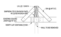
This is my typical detail sans ponywall. Same idea though.
1751909405886.png
 

Part and Inventory Search

Sponsor

Back
Top