Continue to Site

Eng-Tips is the largest engineering community on the Internet

Intelligent Work Forums for Engineering Professionals

  • Congratulations cowski on being selected by the Eng-Tips community for having the most helpful posts in the forums last week. Way to Go!

Shear Wall Force Distribution

Status
Not open for further replies.

Trenno

Structural
Feb 5, 2014
831
Hi everyone,

I've been looking into setting up a few spreadsheets to aid my lateral design sanity calculations. I've come across something that is racking my brain...

My spreadsheet is based upon textbook methods of setting up tables to resolve normal forces and torsional moments into shear forces in each wall. Textbook Example Extract

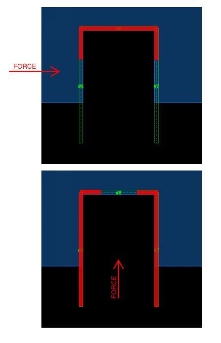
A quick layout of the problem at hand is shown below.

MJLA_Level_3_Screenshot_kcnv5n.jpg


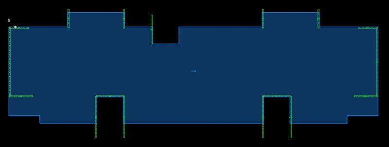
My question: is it conservative or unconservative to perform this method of shear wall distribution with all walls to be considered as isolated and NOT grouped core walls?


Load is attracted to stiffness and we distribute our horizontal shears based on stiffness. Now if I distribute this shear based upon individual walls only and NOT grouped core walls, I may be underestimating the amount of shear carried by the C shaped core's web if the force was acting in the X direction, as the combined stiffness of the C shaped core will be much more than just the web alone, even though the shear will be resisted in the web only.

Then throwing in the notion of effective flange widths, which complicates matters even more. I would then have different stiffness and core centroids due to the 'effective' core properties for each direction of load.

Effective_Flange_Widths_ck63e0.jpg


I'm having trouble piecing this all together! Any help would be much appreciated.
 
Replies continue below

Recommended for you

Found a really good reference, which essentially tells me that I can do my global analysis based upon individual walls and only when I come to design for bending/axial forces I should consider effective flanges.

PS - Would love to know what textbook that chapter is from. It references BS5400 Part 5 for effective width factors but that seems to be the old British Bridge code?


It sounds as though you understand the issues perfectly Trenno. When the composite nature of composite wall assemblies is ignored, the distribution of load to the various walls will be altered. This may produce either conservative or unconservative results for various walls, diaphragms, and foundations.

Some additional thoughts:

- tall buildings are nice because, there, flexural flexibility will dominate with all walls and the way to go is to treat wall assemblies as composite in my opinion.

- very short buildings are nice because most walls will be dominated by shear flexibility. And shear flexibility is unaffected by weather or not wall assemblies are composite.

- It's the intermediate height buildings where these issues are especially difficult to resolve. Unfortunately, most buildings fall into this category.

- for high seismic, ignoring the composite nature of wall assemblies can lead to grossly underestimating the level of load at which flexural plastic hinges will form in the wall assemblies.

- Effective wall widths are annoyingly difficult to deal with in FEM software. They are also pretty gross approximations themselves and nay be less appropriate for stiffness than they are for strength.

- as is often the case, we as designers just have to accept our limited ability to "know" and move on. It's not like there is't already a whole bunch of gross assumptions regarding the non-linear and time dependent aspects of concrete Going into our models anyhow.

- Composite wall assemblies often draw torsion which will be resisted primarily through warping. That warping creates vertical force demands on the foundations. Ehere foundation flexibility will not be explicitly modelled, additional inaccuracies will be incurred.

- To my knowledges, nobody really understands how to properly combine shaft wall flexural yielding with shaft wall torsion in seismic capacity design.

- a closed section shaft mat lose 95% of it's torsional stiffness when the concrete cracks. This is not usually accounted for in our FEM models.

I like to debate structural engineering theory -- a lot. If I challenge you on something, know that I'm doing so because I respect your opinion enough to either change it or adopt it.
 
That's S.S. Ray's concrete text and you're right, it's exceptional for shear walls. MacGregor is good as well.

I like to debate structural engineering theory -- a lot. If I challenge you on something, know that I'm doing so because I respect your opinion enough to either change it or adopt it.
 
Thanks for the thoughts KootK - I agree with all of them.

Building is only two suspended floors however in a very high seismic region (Base Shear = ~45% of Seismic Weight).

In the that SS Ray's textbook example, I can see they are computing shear area, however I've not come across a global analysis method that takes this into account, usually it's just based on flexural stiffness (eg Ix or Iy).

In any case I don't think I should be trying to input 'effective' core properties into my spreadsheet as it will make it more complex, but on the other I don't see how long flanges results in more shear being attracted to those South C shaped stair cores?

 
Trenno said:
however I've not come across a global analysis method that takes this into account, usually it's just based on flexural stiffness (eg Ix or Iy)

Not sure I agree. You're implicitly incorporating shear flexibility if:

1) You're using Etabs, RAM, etc.
2) You're using the "stiffness varies with length times width" assumption that is common for low rise masonry and concrete buildings.

Trenno said:
but on the other I don't see how long flanges results in more shear being attracted to those South C shaped stair cores?

Right. I think the trick here is to incorporate shear stiffness into your spreadsheet such that the numbers will produce a result consistent with your apt intuition. The method below appears in MacGregor's text and is taken from a PCI publication.

For the building under consideration here, I'd recommend just treating all of the wall groups as disconnected rather than composite assemblies. That should be quite accurate given the probable wall aspect ratios that you're dealing with.

I spent a bit of time with a firm renowned for their high-rise work in Toronto, NY, Vegas, and London. I knew that they had a well developed lateral design guide and, when I joined, I could not wait to get my hands on it. As it turns out, they're designing all of their skyscrapers using non-composite wall assemblies. Do I agree with that? Not really. What did I take away from it? There's a pretty good chance that your/my half-assed approach is just as good as anybody else's half-assed approach. Spare yourself the adverse affects of analysis paralysis.

Shear_Stiffness_btgefa.jpg


I like to debate structural engineering theory -- a lot. If I challenge you on something, know that I'm doing so because I respect your opinion enough to either change it or adopt it.
 
Kootk, is this case the same as what stipulated in ASCE that the total lateral shear (V) is taken by shearwalls while the frames will be designed to be able to take 25%V ?
 
Not to my knowledge gotlboys. I believe that the ASCE provision is about ensuring that moment frames in dual systems have enough capacity to promote overall system redundancy. This is just about trying to accurately capture wall behaviour as best we can.

I like to debate structural engineering theory -- a lot. If I challenge you on something, know that I'm doing so because I respect your opinion enough to either change it or adopt it.
 
The calculation method is depend on the flexibility/rigidity of the diaphragm (floor). For rigid diaphragm, the the shear force on each wall is determined on: 1. the eccentricity of force and stiffness center of the shear walls; 2. the wall stiffness; 3 the distance of the wall to the stiffness center of the walls
 
Status
Not open for further replies.

Part and Inventory Search

Sponsor