Continue to Site

Eng-Tips is the largest engineering community on the Internet

Intelligent Work Forums for Engineering Professionals

  • Congratulations 3DDave on being selected by the Eng-Tips community for having the most helpful posts in the forums last week. Way to Go!

Shaft Failure in Translation Gear Reducer of Bucket Wheel – Need Help Identifying Cause

fairyfales

Student
May 28, 2025
7
I’m working on an engineering project analyzing the cause of repeated shaft failure in a translation gear reducer that drives a support wheel of a 400-ton bucket wheel excavator.

System Details

  • Shaft material: 42CrMo4
  • Motor power: 5.5 kW , n=1000 t/min
  • Reducer output power: 4 kW
  • Gear ratio: 150:1
  • Number of support wheels: 16
  • Each shaft supports 1 wheel (load ≈ 25 tons)
  • Bearings: 2 cylindrical roller bearings
  • Support wheel diameter: 710 mm
  • Translation speed: Varies between 1.5 mm/min and 15 mm/min
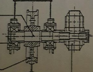
im a bit lost on the calculus , can someone assist me with approaches i should follow and calculus i have to made ? ( it usually breaks from the spline section) 1748440145818.png
 
Replies continue below

Recommended for you

1748446532769.png
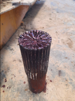
im looking more in the anlysis steps , more than directly assuming the causes , cause i need to make a full analysis , but here is the photograph anyway
 
it probably fails due to the fatigue loading. a very difficult failure mode to sort out.

need an assembly drawing.
then need to some how work out the static and fatigue loads on the shaft.

and you don't need "calculus" for this. or may be you mean "calculations".
 
I would not expect them to put a student in charge of analyzing high-dollar failures in expensive equipment, so this sounds a lot like homework...
 
uniformly dividing a 400 ton load over 16 wheels seems optimistic. a misaligned wheel may be taking a lot more of the load.

please provide bearing locations and wheel load location on the shaft shown above and several sketches of the equipment.
 
it probably fails due to the fatigue loading. a very difficult failure mode to sort out.

need an assembly drawing.
then need to some how work out the static and fatigue loads on the shaft.

and you don't need "calculus" for this. or may be you mean "calculations".
indeed its a fatigue loading and yes i meant calculations .
 
I would not expect them to put a student in charge of analyzing high-dollar failures in expensive equipment, so this sounds a lot like homework...
well the machine still works , even after the failure of one of the shafts , since it has 8 of those . and the frequency is not like 1 day or 1 week .
 
uniformly dividing a 400 ton load over 16 wheels seems optimistic. a misaligned wheel may be taking a lot more of the load.

please provide bearing locations and wheel load location on the shaft shown above and several sketches of the equipment.
1748453162570.png
The bearings are mounted on the shaft surface adjacent to the shoulder, u can conclude that from the 3d model above
 
Do you understand why you would expect it to break at the spline? Did your professor explain that the spline is cut rather than rolled?
 
Is the shaft an OEM parts or a home-engineered replacement?
Is that a gear reducer hanging on the shaft without external support? If so, what is its weight relative to the original design? If there is a rigid or spring-loaded support on the drive, how are you sure it's taking up the correct amount of weight?
How much of the time is it operating with failed or unpowered drive shafts?
Is there shock load being applied during starts or stops that exceeds the original design expectations?
Why is the shaft so horribly corroded? Corrosion contributes to fatigue.
Are the wheel diameters exactly identical and within their wear specifications?
 
Sorry I hadn't seen the photo when I commented.

Wow. Normally I'd have expected a conical failure plane, you've just got simple shear.
 
Do you understand why you would expect it to break at the spline? Did your professor explain that the spline is cut rather than rolled?
due to the spline geometry ?
Is the shaft an OEM parts or a home-engineered replacement?
Is that a gear reducer hanging on the shaft without external support? If so, what is its weight relative to the original design? If there is a rigid or spring-loaded support on the drive, how are you sure it's taking up the correct amount of weight?
How much of the time is it operating with failed or unpowered drive shafts?
Is there shock load being applied during starts or stops that exceeds the original design expectations?
Why is the shaft so horribly corroded? Corrosion contributes to fatigue.
Are the wheel diameters exactly identical and within their wear specifications?
its a home engineered replacement .
the reducer do have a support , and i believe its the original designed one . so its taking the correct weight.
they cant stop the machine mid cycle , so maximum time of operation with a failed shaft is less than 3 hours .
no , the machine been working fine before , so the shock load is definetly within expectations as the problem recently started to occur.
the coloring is not corrosion , its just a red solution they added for extraction .
all the wheels are identical , not sure about about second point .
 
It is very likely your home engineered replacement is not equivalent to the original. Just saying. I've looked at failed home-made replacements to the shafts I design and I can see the differences from several feet away. But they can be subtle if it's not your specialty. And I don't explain them because they are proprietary knowledge.

Most supports are adjustable - so the question becomes whether they are adjusted properly. I've seen plenty of cases where supports are overtensioned to the point they create too much stress in the opposite direction.

Splines are themselves stress risers. On this part they are also on the narrowest diameter of shaft, which virtually assures a possible fracture location. There are a variety of ways to mitigate that issue. Surface stress state, sharpness of cutting radii, surface finish, material hardness and grade (too hard might look good on paper but it can be worse in fatigue due to notch sensitivity). If you intend to continue home-making this part, focus on fatigue initiation modes and locations. It may require a consultant to effectively study that.
well thanks for your reply , but my work here is just to study , i dont own anything , i just want approaches and help on how to do the right relative calculations .


Attachments

  • Failure-Analysis-Gears,-Shafts,-Bearings, Rexnord 108-010.pdf
    813.3 KB · Views: 3
It may be poor machining.
eg: An inappropriate radius on a gullet or other machining mis-operation resulting in high stress areas.
Or a faulty assumption in the original design calculations.
That is, some parameter may be higher than assumed.
 
All of the statistics about the application are insufficient for diagnosing the problem and for making any suggestions except generalities.

Start by doing a stress analysis and finding out any causes for stress concentrations. Get an estimate on the number of load cycles.
 
i just want approaches and help on how to do the right relative calculations .
You need to start from a structured approach. The Ishikawa diagram is frequently used as an initial step in failure analysis to identify possible causes of a failure and the factors that contribute to each cause.

That will identify what you know, and what you need to know.
 

Part and Inventory Search

Sponsor