Hi everyone,
I’m new to this field, so please pardon me if this is a basic question.
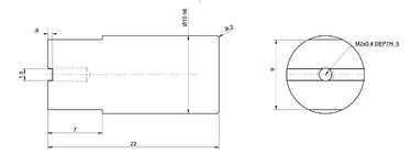
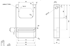
I recently submitted two designs—one with ⌀10 holes specified as H7, and another with a ⌀10 shaft specified as h6 (please see the attached drawings). From what I’ve learned, an H7/h6 combination should result in a clearance fit, but when I received the parts, the shaft wouldn't fit into the hole. The shaft length is only 22 mm. I’ve reached out to the manufacturers for clarification. It turns out the shaft and holes were made by two different companies, so I’m waiting to hear back from them.
In the meantime, I just wanted to confirm: is there anything in my design that might have caused this issue? Or is this more likely a manufacturing deviation?
Any advice would be greatly appreciated. Thank you!
I’m new to this field, so please pardon me if this is a basic question.
I recently submitted two designs—one with ⌀10 holes specified as H7, and another with a ⌀10 shaft specified as h6 (please see the attached drawings). From what I’ve learned, an H7/h6 combination should result in a clearance fit, but when I received the parts, the shaft wouldn't fit into the hole. The shaft length is only 22 mm. I’ve reached out to the manufacturers for clarification. It turns out the shaft and holes were made by two different companies, so I’m waiting to hear back from them.
In the meantime, I just wanted to confirm: is there anything in my design that might have caused this issue? Or is this more likely a manufacturing deviation?
Any advice would be greatly appreciated. Thank you!