Youssef Mohamed
Mechanical
Hello folks, this is my first post in the Eng-Tips Forum
I am working on a project whereas I am required to design a needle valve in a hydraulic circuit to control flow rate. Considering the following limitations in my application:
-The valve must be manufactured due to small size of the project(no use of hoses)
-The valve is operated automatically using MG90s Servo motor (datasheet is given at the end)
-The valve stroke = 10 mm , Frequency of opening and close(with different opening states) is 2 times/second.
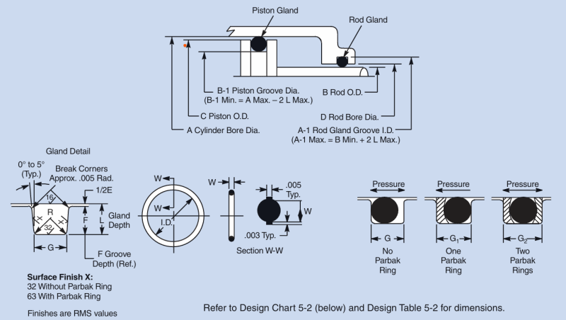
I am using a slider crank mechanism to couple the motor shaft with the needle, but I still need high torque to move the needle (the piston) because of the o ring contact with the manifold (the cylinder). I am only using a piston ring and no rod seals. Furthermore, I have manufactured the valve using manual conventional machines ( Turning, Milling), yet I have ordered a CNC work, but there is a little hope to achieve Parker dynamic O ring standard specs for surface finish and roughness:

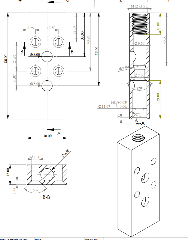
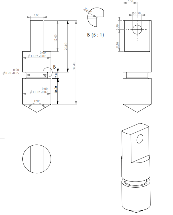
Is there any solution for the torque problem? Different design suggestions are absolutely welcome. here are the designs of both Needle and Manifold(the needle slides in non-threaded hole and the threaded hole shall be sealed well).


Unfortunately I haven't yet finished the designs of slider and crank.
Another Question: I am also required to design a ball check valve(spring-loaded) within the manifold so that I have the 9 mm diameter spherical geometry . Does using the spherical space have any advantage over a conic geometry??
MG90s servo motor datasheet:
I am working on a project whereas I am required to design a needle valve in a hydraulic circuit to control flow rate. Considering the following limitations in my application:
-The valve must be manufactured due to small size of the project(no use of hoses)
-The valve is operated automatically using MG90s Servo motor (datasheet is given at the end)
-The valve stroke = 10 mm , Frequency of opening and close(with different opening states) is 2 times/second.
I am using a slider crank mechanism to couple the motor shaft with the needle, but I still need high torque to move the needle (the piston) because of the o ring contact with the manifold (the cylinder). I am only using a piston ring and no rod seals. Furthermore, I have manufactured the valve using manual conventional machines ( Turning, Milling), yet I have ordered a CNC work, but there is a little hope to achieve Parker dynamic O ring standard specs for surface finish and roughness:

Is there any solution for the torque problem? Different design suggestions are absolutely welcome. here are the designs of both Needle and Manifold(the needle slides in non-threaded hole and the threaded hole shall be sealed well).


Unfortunately I haven't yet finished the designs of slider and crank.
Another Question: I am also required to design a ball check valve(spring-loaded) within the manifold so that I have the 9 mm diameter spherical geometry . Does using the spherical space have any advantage over a conic geometry??
MG90s servo motor datasheet:
