This paragraph?
1503-44 said:
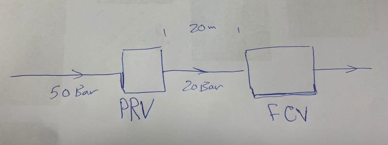
A downstream pressure regulator can be set to 20b. It's flow will then be dependent on the upstream pressure. If that upstream pressure increases, the PRV will close a bit to hold 20b and flow through the regulator will tend to decrease. I say "tend to decrease", because the upstream pressure went up. Now the differential pressure dP across the valve has increased, so the PRV flow will go to whatever flow corresponds to that new dP. The upstream system plays a part here. The PRV inlet pressure just went up. That might slow the flow upstream, but it might not. If the upstream segment of the system holds the same flow rate with the higher pressure at the PRV's inlet, then the new pressure at the PRV inlet will not change any further. If the upstream flow rate decreases, due to the higher PRV inlet pressure, then flow through the PRV changes to match that upstream flow rate. If that results in a 20 bar downstream pressure, it's done. If not, the regulator opens or closes again to match 20b discharge and this cycle PRV-upstream cycle starts again. Whenever it is cycling, it is adjusting its flow rate.
Please note that I didn't say "flow is
controlled" by the PRV. I said it (flow) is
dependent on the upstream pressure. Flow through the regulator is solely dependent on the pressure differential across it, just as it is for every flow element (something having flow). It does not matter what it is. Even a FCV. A FCV has a Flow rate setting, but its positioner controls its %Open to allow the differential pressure to change and drive a flow through it. If the flow equals its setting, position changing stops. In the case of a PRV, The same thing happens, but instead of stopping its positioning action at a certain flow rate setting, it stops when (in this case) outlet pressure is sensed at 20bar. The flow through the PRV will then correspond to whatever flow across its %Open area that its differential pressure at the moment will drive. Only its dP, not the upstream pressure, and its %Open, determined by where it should be to get a 20b output determine what its flow will be. No matter what the upstream pressure is at the time, The PRV does not care. It works to hold the 20b downstream, upstream pressure be damned, and the resulting dP drives whatever flow across it.
OK, say the PRV changed its flow rate by virtue of its need to hold the 20b outlet pressure. Assuming its a steady state flow in the system, holding that flow rate at the PRV will try to force all other flow elements in the system to do whatever they need to to feed the ZPRV that flow rate.
If upstream pressure needs to increase, it will look for more pressure. Maybe an oil well can supply it. So we look at the Pressure vs flow curve of the well. If the particular flow required in the upstream piping, now equal to the flow through the PRV can be supplied at some pressure, the well moves to that point on the curve, and it's done. If it can't reach the new flow, it meets what it can and delivers a flow that it can at whatever higher pressure it can reach. So now that flow rate is heading to the PRV. When it gets to the PRV, the PRV senses there is a flow rate change through it when (if) the 20B rises, or falls in response to that well flow rate's effect on the inlet pressure of the PRV and the new differential pressure across it. It changes position to hold 20b. That changes the differential pressure across it again along with determining a new flow through the PRN. That new flow rate now heads upstream to the well to see where that hits the well P-Q Curve. Now we look at the downstream half of the system.
The same thing is happening there, the new flow rates through the PRV are having similar effects on the downstream half of the system. The inlet pressure on the downstream half is 20b. The downstream system tries to make its outlet pressure to correspond to whatever it should be to pass the PRV's flow rate through its part. If the downstream outlet is OK with that P and Q, its done. But let's say that the pressure rose (or dropped if you want) so some controller there, a human being, goes out and nearly closes the outlet, that increases pressure there, which slows the flow there. The pressure starts increasing with flow rate dropping it in that half of the system. These effects continue moving upstream until they reach the 20b sensor and that changes the %Open of the PRV such that outlet pressure is held at 20B. Of course that changes the flow through the valve. Now we have to look at the upstream half to see what that does to the oil well pressure and flow rate. Etc. Etc. The cycling continues until some stable solution is found that satisfies all dP, 20B and the total system pressure drop that results in all flow elements reaching the same Q,
OR it continues cycling forever. The gains in all the PIDs have to be set within ranges that allow the valves to position properly and long enough to reach stability. If they are not adjusted properly to allow that, cycling may continue forever, even though a stable solution exists. Its just all valves won't reach their stable positions at the same time. Some might need more gain, others less. At times it can be a bit tricky to get them all right. One reason to keep the numbers of PIDs and valves and other things that cause glow and pressure to vary as few as you can.
Did that make sense? I can make a simulation in Stoner that will clearly show all of these effects, if you need additional proof. I can put in a VFD pump, tank or an oil well to feed it and a tank or injection well or a constant pressure or constant flow Node, or an entire other system at its outlet. Or all. As long as there is at least one source and one sink, I can sim it.
--Einstein gave the same test to students every year. When asked why he would do something like that, "Because the answers had changed."