Continue to Site

Eng-Tips is the largest engineering community on the Internet

Intelligent Work Forums for Engineering Professionals

  • Congratulations 3DDave on being selected by the Eng-Tips community for having the most helpful posts in the forums last week. Way to Go!

Sequence of press fits

Status
Not open for further replies.

engineerfin

Automotive
Feb 22, 2015
62
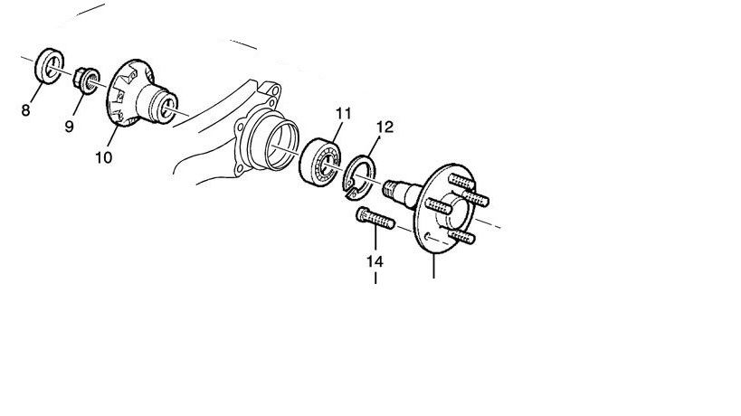
In this example, there are a couple of ways of completing the task of replacing the bearing in the field. The factory does not recommend the field operation, they recommend removing the control arm and use a press (major job and super time consuming). The question is which field method would be the best. The press fit between the bearing and spindle and bearing and hub is .001+
1. Freeze spindle (in refrigferator 0-10F) - heat bearing at 200F in oven - slide bearing onto spijndle. Since these parts are small and removable a press could be used. Question would heat be bad for the bearing. Then as an assembly, freeze spindle and bearing - heat control arm housing and drive spindle/bearing into housing. - Question would the driving force from a hammer damage the bearing.
(note:spindle is not long enough to to pulled thru via threads and a nut.

2. Freeze bearing (I have noticed moisture inside bearings when doing this even is bearing is in a sealed bag. could this moisture cause failure down the road) - heat housing and install bearing.
Here is the problem with this method - Freeze the spindle but what do you do with the bearing? cant really heat it.
Good thing about this method is the bearing can be pressed in using a ball joint. Spindle is too large for a too like that.


Replies continue below

Recommended for you

The factory outlines and recommends one procedure only.

Do you accept responsibility for using a different procedure?

... When it goes sideways?

Is this part of an airplane?


Mike Halloran
Pembroke Pines, FL, USA
 
Well, when you follow the factory instructions you have to disconnect and open the hydraulic system (brakes). Good thing its not an airplane. Sometimes there are ways to solve a problem that are better then others. Dont assume that the manufacturer has the last word or is the most intelligent. Also factory manuals are usually not written for the end user, they usually require special tools and equipment only found in factory repair garages.
 
You never want to apply the type of forces used with a mechanical press fit if there is the possibility of those forces being transferred across the bearing rolling elements. The best option is always to thermal fit the bearing races if an interference fit is required.

With example shown, there is a retaining ring that holds the outer bearing race in place in the suspension arm, and the retaining ring likely cannot be installed with the hub fitted inside the inner bearing race. So it seems likely the bearing needs to first be installed in the suspension arm.
 
tbuelna, good point about the thermal press, another reason not to believe the factory manuals, no mention of that. I agree. As far as the snap ring, good eye, its a safety feature and it can be installed with either scenario. It goes on the hub first either when the bearing installed on the hub or when the hub in pressed into the bearing inside the control arm.
 
Hi engineerfin,

"(The snap ring) goes on the hub first either when the bearing installed on the hub or when the hub in pressed into the bearing inside the control arm."

Have you taken this apart yet?

It looks to me like the snap ring fits in a groove in the Control Arm, not on the hub.
Functionally that is where it is needed, as a failsafe for the bearing sliding axially in the CA..
The bearing inner race is captured axially when nut 9 clamps drive flange 10 against unmarked hub.
Like Tbuelna said, the snap ring would likely have to be installed after the bearing is in the control arm, and before the hub ( item number cut off in picture ) and is installed.

The few-to-several 1000 lb forces needed to Install the bearing in the CA and to pull the hub into the bearing likely could be provided with a large threaded rod. Fixtures/adapters might be made from bits from Loew's plumbing department. Also as Tbuelna said, the force must be applied to the race being installed. Doing that while Removing the bearing from the CA may prove difficult, as the inner race may be all that is exposed, but I guess you will replacing it anyhow.
 
Yes I have taken these apart. (see attachment) The snap ring can be installed either way. As a matter of fact, it is the first to be removed, it just dangles on the spindle until the bearing is removed(or installed). I have actually seen people forget to put the snap ring on the spindle first, then install the bearing. They wind up spreading the snap ring over the bearing. It works. Jackscrew can remove bearing. So to do the installation correctly, neither method really works because you cant really press the bearing on the race that needs to be pressed. On the other hand, you can get .001 shrinkage by freezing the bearing(I measured it), not sure what the hear gain would expand the housing but the press fit is .001 so there would not be 1000 lbs of force.
 
 http://files.engineering.com/getfile.aspx?folder=6f51fdff-451c-472b-b923-179b6074e749&file=DSC_1009_026.JPG
Tmoose, thats fine and dandy, what about the spindle. Thats the hard part. I think the only way to do it in the field is to have the spindle and bearing together (snap ring dangling between the two), freeze the spindle assembly, heat the housing, and tap it in with a hammer. At the worst it would be a zero tolerance. It would have to be a quick slam because the heat of the housing would heat the frozen bearing. Maybe dry ice would be better but its dangerous. A balljoint press/clamp would be great but the spindle hub is too large in diameter.
 
Ok, check out my new invention. It pulls the spindle thru the bearing. Threads on to the end of the spindle and then used a nut/washer and threaded rod to pull the spindle thru the bearing. Sure it is putting force on the inner race but so will axial loads from a 4000lb car going into a corner.
 
 http://files.engineering.com/getfile.aspx?folder=976d5414-5e6d-4a71-98a6-53122466ed03&file=TOOL.JPG
"what about the spindle. Thats the hard part...."

A piece of pipe with ID .01" larger than the bearing ID, and nut number 9 would pull the spindle into the bearing (already installed in the hub). It might take a few pieces of pipe of various lengths.
An alternative is welding some all-thread to an old #9 nut with an intermediate transition. This would permit pulling the spindle into the bearing in one continuous pull, applying force only to the bearing inner race.

A little like this -

When assembling shrink fits I want to have Plan B all set to go to mechanically seat the parts if the pieces stick half way home.
 
engineerfin-

The combined radial, axial and moment forces applied to that duplex angular contact ball bearing during operation have been carefully analyzed. On the other hand, you have no way of knowing what forces will be applied to the bearing using your installation approach. It would not take much excessive axial force applied to the bearing balls to cause brinelling damage to the race surfaces. When that happens, the bearing will quickly suffer spalling failure.

You should first thermal fit or press fit the new bearing into the control arm by applying force only to the outer bearing race. Install the retaining ring. Then you can thermal fit or press fit the hub into the inner bearing races by applying force between the threaded end of the hub and the inner bearing race end face. This way no axial force is applied to the bearing balls. Like Tmoose says, make a long outer sleeve that has the same diameter as the inner race and an internal thread at the other end. Then make a jackscrew that connects to the hub flange thread at one end and mates to the internal thread in the sleeve. This device will pull the hub shaft into the bearing inner race without placing any load on the bearing balls or outer race.
 
I'm guessing the interference fits could be overcome by a peppy pneumatic impact hammer, so the various press tools made from pipe could be replaced by two long ones. One with inner race ID clearance, and one with outer race OD clearance. Piloting features would require some thought.

Similar to this very successful in-situ ball joint installer.

 
Status
Not open for further replies.

Part and Inventory Search

Sponsor