Continue to Site

Eng-Tips is the largest engineering community on the Internet

Intelligent Work Forums for Engineering Professionals

  • Congratulations waross on being selected by the Eng-Tips community for having the most helpful posts in the forums last week. Way to Go!

SEPIC converter design

Status
Not open for further replies.

Peter05

Student
Sep 5, 2021
2
Hello,

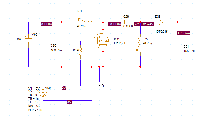
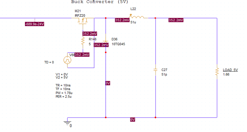
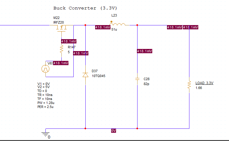
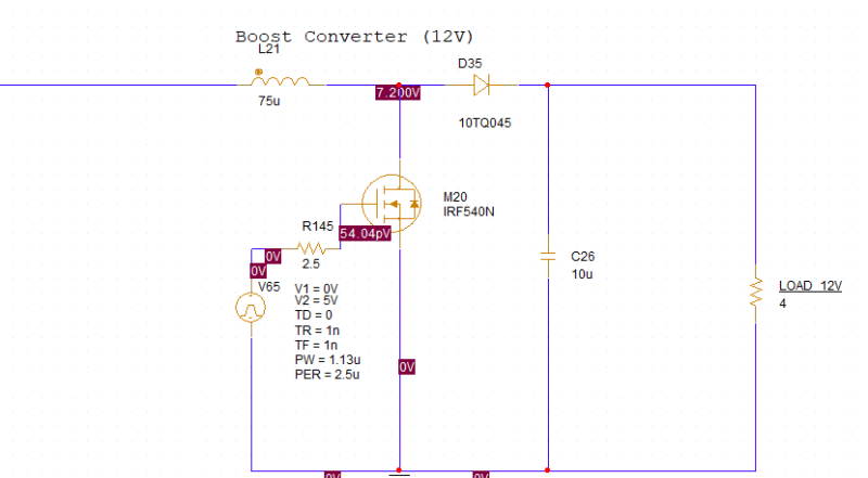
i would like to design a SEPIC conveerter with input voltage ranging from 3Volts to 19 Volts . On its output will be connected three DC-DC converters ( 1 boost and 2 buck converters , their image is attached) and the output voltage of the SEPIC should be araound 8.4V.Could you help me with the design ?

Thank you.
buck1_yhkadz.png
buck2_xq4qyk.png
boost_pu02ot.png
overall_eymmm4.png
 
Replies continue below

Recommended for you

What's stopping you from using one of the myriad of available chips and following their datasheets? Unless you're truly trying to do something different, the datasheets have pretty much everything you need to know to build up a basic converter. The fact that you're hooking up multiple converters the the output of the SEPIC only matters in terms of how much input capacitance they have (i.e., how much output capacitance the SEPIC sees).

Dan - Owner
Footwell%20Animation%20Tiny.gif
 
My first try is this circuit :
cir_jn4t76.png

But my circuit presents a strange response.
For pw =4.8u the response on the output is this (about 6.5V):
before_tai0e0.png

and the response for greater pw(e.g. 5u) is like this :
after_ombvwr.png

Both far away from ~8.4V.
 
Status
Not open for further replies.

Part and Inventory Search

Sponsor