Hello,
Please also read :
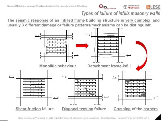
I am glad that this topic is discussed here because in my opinion the nonstructural elements made from masonry (infilled walls or the walls that are between slabs without rc frames) are the most vulnerable part of a building during an earthquake. I think it's more probable that a masonry partition wall will fall (and have a great risk of killing people) vs a new designed RC structure to collaps.
In my area seismic design code is specified that you should only consider the negative effects of the masonry partitions - like global torsion, soft story's etc.
Also as the structural engineer of the RC building you have to check for the stability and capacity for all of partitions. There is a big problem here: you can check the infilled walls for out of plane forces (seismic force perpendicular to the wall or wind) and for in plane forces (modelling with diagonal struts and check the limits) but for walls that are not infilled
how to do you design for the interaction with the RC structure ? This is clearly specified in my code that you should check for the interaction with the building deformation...
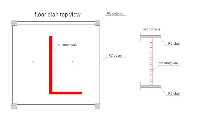
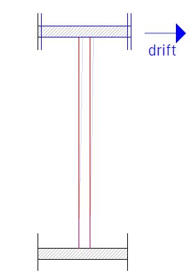
Say for example that you have the story drift on 1%. For a 3m level there will be a lateral movement (drift) of 3cm. Lets say that we have the case from the picture below - in the left is the floor plan and in the right is a section trough the masonry wall represented with red color :
Now if the earthquake happens and we have a drift of 1% the top slab will move 3cm left/right. What happens with the masonry wall ? It will drift (shear+bend) on top with the slab 3 cm ? I dont think so because if you calculate the necessary force in order to displace it 3cm the force is huge and the wall can't take it.
So it's clear that something has to break... I think that the shear connection (the mortar) between the slab and the wall (the top contact surface) breaks and the wall will not have any more the imposed displacement on top from the structure but only the seismic force from its on mass. If this is the case in my example because top end of the wall (top as you look at the plan) its free (the bottom has an perpendicular wall so lets say this end is fixed) and now the connection with the slab is gone its a very bad situation because as you look from the side of the wall top is free, left is free, bottom and right simple fixed.. Bending capacity is reduced to almost 0... what do you do then ?
Option 1. Use near the slab and wall connection steel angles.. Yes this is good for calculating bending out of plane because the top is fixed BUT then the 3 cm displacement is for sure transmitted (imposed) to the wall.. the wall cant bend that much, what happens then ? I think that the bricks that are in contact with the steel will break from pressure.. and then we are back to start with no connection on top and a great risk of instability.
Option 2. At the free end of the wall (as you look at the plan: on top) make a small RC column fixed bottom and top with a dowel so that can take only shear.. Now the elevation of the wall is : bottom, left, right fixed and top free. It's better but as the column is fixed to the slab it will deform with the structure.. the key thing (I think) is to use a very soft dowel so the slab movement will not induce a 3cm top displacement of the column rather a smaller one (by bending of the dowel). If you can solve this on paper maybe it's a good choice but to execute it (build it) to perform this way is tricky...
Option 3. I don't know, maybe you have some ideas...
Btw this is also a problem for the infill walls ...
This is only a small example, there are many cases like this that are difficult to solve (if they are solvable).. This is why I think that masonry partitions are the greatest danger in case of an earthquake, especially because in my area the architects practice thin walls (15cm), 3 m height and God know how long (3-6m)...
Any input on this topic will be great, thank you and btw Hi KootK.