Continue to Site

Eng-Tips is the largest engineering community on the Internet

Intelligent Work Forums for Engineering Professionals

  • Congratulations The Obturator on being selected by the Eng-Tips community for having the most helpful posts in the forums last week. Way to Go!

SAP2000 - Problem in Insertion Point? 2

Status
Not open for further replies.

raobn

Civil/Environmental
Nov 9, 2020
6
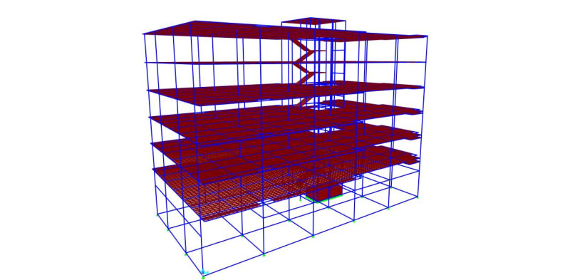
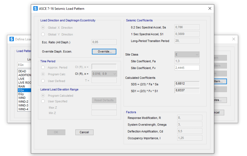
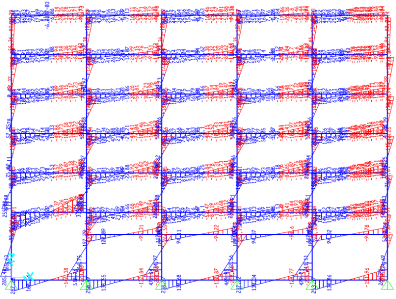
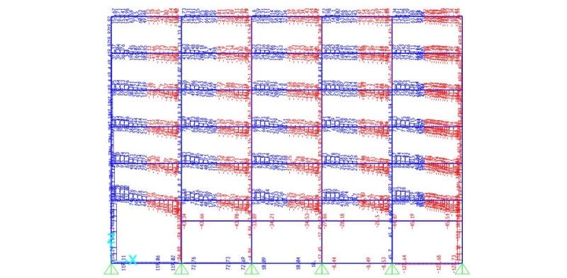
Hello everyone, I'm a civil engineering student and currently having a problem while modelling a 6 story reinforced concrete special moment resisting frame building. The analysis is about the equivalent static lateral force and response spectrum. I follow the ACI 318-14 and use cracked section for the column, beam, and slab. And I follow the ASCE 7-16 for the seismic analysis.

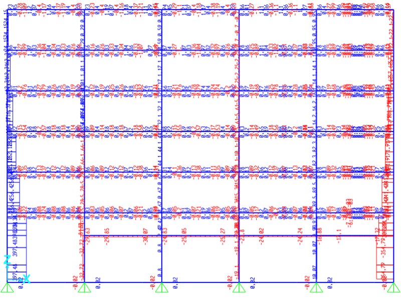
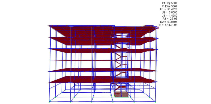
So I make my models with the insertion point for the frame set as "centroid" and "top center". The first model's time period is higher than Cu.Ta and the displacement due to earthquake load is large, but the axial load on the beam is low. For the second model, the time period is lower than Cu.Ta and the displacement due to earthquake load is also low, but the axial load is higher than allowed axial load for SMRF structure (the axial load should be lower than Ag.fc'/10). I read a lot from the forum that we should set the frame insertion point as centroid so there wouldn't be large axial force on the beam, but when I do that, there are another problem (building time period and large lateral displacement).

Is the problem from my model is specifically about the insertion point or are there something else I should consider to check on my model? I hope someone can guide me, I am currently using SAP2000 v23 to model my building. Sorry if there's something wrong in my question/post. Thank you very much.
 
Replies continue below

Recommended for you

It's difficult to be certain about what's happening. But, I've seen similar things like this before. Are you using a diaphragm? If so, the combination of the diaphragm with using the insertion point as the top of the beam could be causing the problem.

One of the things we struggle with as engineers is how to model accurately enough to get the results that we want, but not so accurately as to create unnecessary complexity. If the program is creating a diaphragm at the TOP of the beam, that's probably more complexity than we would normally want to do. Typically, we model our diaphragms and beams and such at a single elevation. It's not 100% correct, but it's expedient and gives us the type of results we're looking for.

 
Thank you for your suggestion, I am using diaphragm on my model and I use thin shell to model my concrete slab.

I've tried assigning the diaphragm on each storey of the building and set the insertion point as "centroid" to reduce the complexity that might be caused because I set it as "top center" before, but the result is still the same as before (larger storey displacement and time period than the "top center" model). I apologize because I forgot to attach my model's SDB file if it helps.

I really appreciate your response, I will learn more about assigning the diaphragm constraint on SAP2000.
 
 https://files.engineering.com/getfile.aspx?folder=fd17d013-2500-49e0-9f39-a4e36e31c72b&file=Six_Storey_Hospital_Building.sdb
check your auto length offsets and frame meshing as well
 
Hi, thank you for your suggestion on frame length offsets and frame meshing. I've tried to divide the frame on every intersection with other frames or shell sections (manual mesh) on other model but I'm still getting large storey displacement due to seismic lateral load. I've also assigned rigid zone factor 1 because I'm assuming rigid connection on my reinforced concrete building model.
 
post some pics isometric of your building model
with load display for your ELF also axial, shear and moment diagrams

someone had a similar problem recently with lateral loads not being transferred through building

and resetting all the auto frame offsets and only having auto mesh at joints selected for all frames
seemed to corrected the load path but i cant confirm if it ' corrected ' the analysis


Thank you for your suggestions, here are the isometric view of my building analysis model. I apologize if there are still some mistakes in showing my model.

model_isometric_view_kkxykr.jpg


So my building is a 6 storey building and I model the base support as pin restraints. I also model the building's stairs as thin shell and the elevator pit wall as thick shell because it is 300 mm thick and 1550 mm tall. The elevator column is L shaped, so I just use the L section of steel frame and set it's material as concrete.

model_isometric_view_2_glutn8.jpg


I've assigned the equivalent lateral force using ASCE 7-16 lateral load pattern in X and Y direction. For the occupancy importance I'm using the value of 1,25 because it is a hospital building.

ELF_load_pattern_per7gz.png


And here are the axial, shear 2-2, and moment 3-3 diagram due to ELF in X direction of my model (in kN, m, C unit).

Screenshot_2021-05-22_181746_azptvk.png


Screenshot_2021-05-22_181902_jj4ylk.png


Screenshot_2021-05-22_182042_tfqovm.png


Thank you for your input on this problem, I will try to look up the thread about lateral loads not being transferred to the building on this forum.
 
is this the model with the center insertion points?
post the deformed shape under lateral and story drift plot

if you notice your beam line without the floor has consistent axial compression
and your beams with the floor is changing between tension compression at your manual mesh breaks

post the results for a model with just 1 area object for the floor with automesh

it looks like from your axial diagram your slab is not draping the axial to the intermediary beams for each individual frame to act
and its only using your start and end columns
 
Thank you for noticing the changing tension-compression force on the slab, the model is indeed from the center or centroid insertion point of the frame section. The model with "top center" insertion point has significantly high axial force on the beam. This is the axial force on the model with "top center" insertion point.

ELF_axial_top_center_zpul0f.jpg


And this is the axial load on my model with slab meshing (on the model with "centroid" insertion point). I just noticed the changing tension-compression force is might be due to the slab meshing.

ELF_area_object_axial_egs3xf.jpg


Here are the deformed shape of my building model due to ELF in X direction (joint displacement in mm unit). On the model with insertion point set as "centroid" the displacement on top storey is 91,4828 mm, but on the model with "top center" insertion point the displacement is only 43,2591 mm.

ELF_deformed_shape_rw3yix.jpg


Again, I apologize for my limited understanding on intepreting the output of SAP2000. Thank you for your replies.
 
Hi, I'm still trying to find the main cause of this problem, but I will give an update if I found the solution!
 
i would try by removing or changing elements and seeing the change in behaviour
-remove the area obj
-dropping the stiffness of the area obj

if you find out the area obj is cause and there is no solution maybe
you can opt for alternate model of the slab using horizontal bracing to simulate your diaphragm
and applying loads directly to the frames?
 
Status
Not open for further replies.

Part and Inventory Search

Sponsor