Tek-Tips is the largest IT community on the Internet today!

Members share and learn making Tek-Tips Forums the best source of peer-reviewed technical information on the Internet!

  • Congratulations JAE on being selected by the Eng-Tips community for having the most helpful posts in the forums last week. Way to Go!

SAP2000 - Modeling Box Section with shells elements 1

Status
Not open for further replies.

Okeore

Civil/Environmental
Joined
Jul 20, 2019
Messages
5
Location
BR
Hello colleagues,

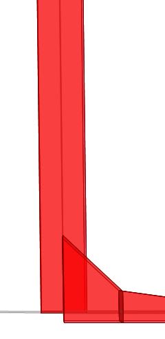
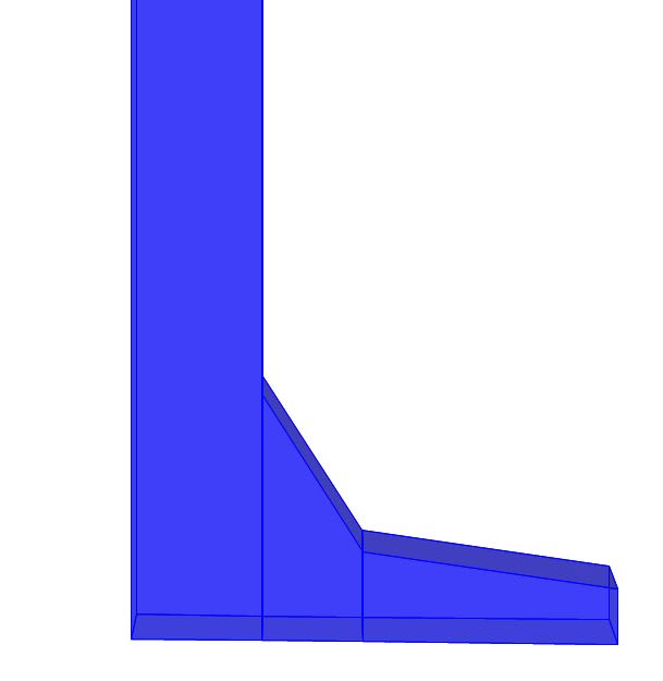
I'm trying to model a concrete box section with shells in sap2000. I must do this with shells elements and this section has variation of thickness.

The thickness of the slab increases of 10 cm to 15 cm and then to 40 cm in the joint with the vertical element.

My problem is to model it at the connection between the vertical shell element and the slab. Cause the shell don't allows to use the commands "End (Length) Offsets" and "Insertion point".

So I thought I can model elements as frames, to use both commands that I said and then to use the command "Convert Lines to Areas". But this last command isn't working.

Anyone knows how I can do that?
 
Can you provide a drawing of what you are trying to achieve?

“Any idiot can build a bridge that stands, but it takes an engineer to build a bridge that barely stands.”
 
Ok.
The first image is of the problem to model this kind of structure with Shell elements. I can't adjust the joints.

Shell_he2740.jpg


The second image is of the same structure modelled with Frame elements. I can adjust the joint of the structure when I'm using frames.

frame_q2hu6z.jpg
 
I don't have a clear picture of what this is.....but I would think any sort of "concrete box" could be modeled with plate elements available in most FEA packages I am familiar with. Although the mesh needs to be much finer than what I am seeing here. Also, a change in thickness is no big deal either.

 
I think I was not clear enough. I don't want to model just 1 box section. It is a multicelullar box section.

You didn't understand. The images are different from each other. Look the first image, the bottom shell are conecting on the centre of the vertical shell. This is wrong.
 
I’ll agree with you that it’s not clear enough and that the first picture is wrong. I honestly can’t even tell if I your box is supposed to be hollow or not. If you’re trying to model a solid beam of varying cross section with shell elements my advice would be don’t. If the beam is solid frame elements would probably be more appropriate, solid HEX elements would be best.

If it’s a hollow box my best advice at risk of sounding trite is model the shells at the correct location, which you haven’t done in the first picture. Not helpful there I know.

“Any idiot can build a bridge that stands, but it takes an engineer to build a bridge that barely stands.”
 
You are talking about a box culvert (I guess).

In that case you would need to model the boundary shell of the cover slab to the adjoining wall as thicker.

You may be able to use "Area Thickness overwrites(Shell)" to define an area overwrite.

You could use the average thickness in the last shell and you would still be ok.

Finally, you could do a frame and analyze that instead - with line elements of variable thickness, analysis results per 1m strip (easy).

Don't extrude a 2D frame to produce shells.

SAP2000 is not the software of choice for these kind of structures. You could try ROBOT or MIDAS Civil (or similar).
 

Yes, exactly what you said. I need to model in the correct location. But I think it is impossible to do this in SAP2000 with shell elements.
 
Status
Not open for further replies.

Part and Inventory Search

Sponsor

Back
Top