In CAD "sheet metal" means - constant thickness and single-radius bends in one direction. Basically, it's only considered sheet metal if you can make a piece of paper form the same way without wrinkling or tearing.
At the least the fillet is a bend in two directions. See
and note that a cylinder and flat plane have zero curvature, which is why you can easily roll a flat sheet into a cylinder. The fillet has a negative curvature and requires deformation of the metal to form. This video has a more interesting discussion (caution: video may induce feelings of hunger)
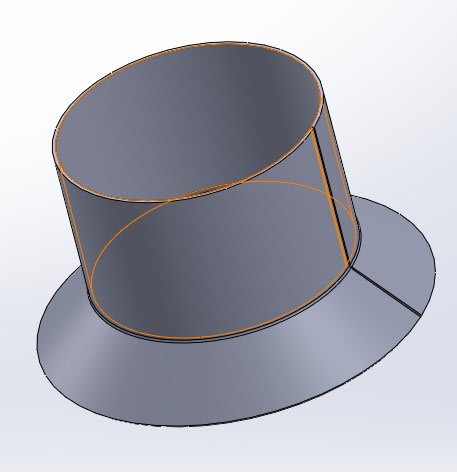
In combination the cone and cylinder form a composite that is also relatively toroidal, so the combination is also not zero curvature and cannot be formed from a flat sheet without deformation.
Some software, like SW, will stretch (pun!) the definition and create desperately faked "flat" patterns that cannot realistically be used for anything other than a first cut rough approximation of the material to be used. To do a reasonable job requires an FEA model to map the stretch, shear, change in local thickness, and sometimes local work hardening. On top of that the conversion of the flat pattern to a compound curvature part is highly dependent on the method used (skilled worker, die forming, stamping, hydroforming, et al. Each requires a different "flat pattern."
If there is a problem with "sheet metal" software in defining the part then it's often a part that is not created with sheet metal processes that preserve material thickness. It's often like looking at a vacuum formed part and deciding what that flat pattern is like - hint: no matter the final shape the flat pattern is a much larger sheet, usually a rectangle, that is flat.
There should be no cracking due to welding just because the part is used in a hot environment. There might be cracking because the part is not uniformly heated, causing high stresses in the area of the stress concentration where the two sections meet. This can happen if the part is welded or formed.