Continue to Site

Eng-Tips is the largest engineering community on the Internet

Intelligent Work Forums for Engineering Professionals

  • Congratulations cowski on being selected by the Eng-Tips community for having the most helpful posts in the forums last week. Way to Go!

Ring Type Flange from Rolled Strip

MHS1988

Mechanical
Jan 6, 2024
16
Hello everyone,

I’m seeking clarification on a fabrication method for a ring-type flange with the following dimensions:
  • I.D.: 1100 mm
  • O.D.: 1250 mm
  • Thickness: 135 mm (no hub)
  • Material: A516-70
My fabricator plans to cut 75 mm-wide strips from a 140 mm-thick plate, then roll them into the ring. I’m concerned this approach orients the grain structure incorrectly. I believe the proper methods would be either:
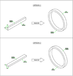
  1. Cutting 140 mm-wide strips from a 75 mm-thick plate and rolling them (so the flange axis aligns with the plate’s original surfaces), or
  2. Cutting a full ring directly from the 140 mm-thick plate (avoiding rolling altogether).
The fabricator argues that ASME VIII-1, Appendix 2, Clause 2-2(d) only applies to flanges with hubs and claims their method saves material.

My questions:
  1. Is rolling the strip in the fabricator's proposed direction technically acceptable despite the grain orientation concern?
  2. If not, are there code provisions (beyond Appendix 2) or other references that explicitly address this?
I’d appreciate any insights or experiences you’ve had with similar scenarios. Thanks in advance!
 
Replies continue below

Recommended for you

How do you plan to weld the flange to the cylindrical shell?
Shell thickness and material?
 
If you simply wanted to cut the flange from plate you would use 140mm plate wouldn't you?
Isn't this the same orientation as his original solution?
But in this case the "LT" and "ST" very around the ring.
At least with his approach they will stay constant.
Is he cutting across the plate or along it?
Either way the "ST" is still the thickness.
 
How do you plan to weld the flange to the cylindrical shell?
Shell thickness and material?
It's a slip-on girth flange. The weld will be according to Figure 2-4 (8) of Appendix 2.
Shell thickness is 15mm and the same material as the flange is being used, A516-70.

If you simply wanted to cut the flange from plate you would use 140mm plate wouldn't you?
Isn't this the same orientation as his original solution?
But in this case the "LT" and "ST" very around the ring.
At least with his approach they will stay constant.
Is he cutting across the plate or along it?
Either way the "ST" is still the thickness.
I guess the difference is that in just cutting a ring from the plate you wouldn't introduce extra stress from rolling and bending.

He is cutting the strip along the plate.
 
During design, everything matters. PWHT is key in this case.

At first glance I don't like your design.
 
MHS1988, I did have ring type flange from plate but more that 20 years ago. Lost the detail record. What I can recall is , the long strip shall be cut in the longitudinal direction, i.e., following the fiber or grain direction, so you will roll in the hard way to form a ring, similar to roll the hard way for shell can.
You will need to calculate % of elongation to determine PWHT, and for weld thickness greater than 38 mm, perform PWHT. For sure RT is needed, and probably do a PT to check fine cracks on all surfaces due to rolling.
The other issue is, tensile and yield strength reduced for thicker raw plate. So using thinner raw plate may be preferred. Check with Section II.
Both 75 mm or 140 mm plate look ok to me. But cutting a ring from plate ? Not preferred. The same reason why shell can is preferred rolling in the hard way (transvers direction) to have fiber direction all around.
Come to the next question that many people will not know: Can shell can be rolled in the longitudinal direction to build a vessel such that a shell can is 20' long in lieu of 8'or 10' long ? Yes. It is the preferred design by CB&I to enhance fatigue life due to bulging of the shell for coke drums.
 
i.e., following the fiber or grain direction, so you will roll in the hard way to form a ring
Can shell can be rolled in the longitudinal direction to build a vessel such that a shell can is 20' long in lieu of 8'or 10' long ? Yes. It is the preferred design by CB&I to enhance fatigue life due to bulging of the shell for coke drums.

The reasoning for Appendix 2-2(d)(1) I believe is more on avoiding opening up the laminations as a result of plate manufacturing (this is discussed in ASME BPVC Companion Guide). It is not really about the grain direction (metallic grain structure) as it is kind of scattered and random throughout the plate. Having the surface of the plate be parallel the axis of the flange may open up the laminations by the bending stress on the flange.

For sure RT is needed, and probably do a PT to check fine cracks on all surfaces due to rolling.
Considering above, I would include 100% UT lamination check to check if laminations are present (See Mandatory Appendix 20).
 
From some of the replies, I gather that my initial explanation of the situation may not have been clear enough. To better illustrate the situation, I’ve prepared a sketch showing two proposed methods for rolling this ring, which will later serve as a slip-on flange:
  • Option 1: The method suggested by the fabricator.
  • Option 2: The alternative I recommended based on my understanding.
I am under the impression that the fabricator’s approach (Option 1) might be prohibited or considered bad practice in certain standards. However, if there’s no explicit restriction in the code or industry references, I’m open to proceeding with their recommendation.

Here is the sketch:
 

Attachments

  • SKETCH.png
    SKETCH.png
    51.1 KB · Views: 5
(Option 1) might be prohibited or considered bad practice in certain standards
It is implied already in other parts of the Code considering lamination concerns on plates. It is not due to the grain structure. Based on engineering judgment, Option 1 should be avoided.

Red line is lamination :
1746175152235.png
 
It is implied already in other parts of the Code considering lamination concerns on plates. It is not due to the grain structure. Based on engineering judgment, Option 1 should be avoided.

Red line is lamination :
Thank you so much.
 
I insist: "More info: design pressure and temperature?"

And now: The diameter of the bolt you are considering is?

Something is strange here
 

Part and Inventory Search

Sponsor