Continue to Site

Eng-Tips is the largest engineering community on the Internet

Intelligent Work Forums for Engineering Professionals

  • Congratulations cowski on being selected by the Eng-Tips community for having the most helpful posts in the forums last week. Way to Go!

Rigid Split Coupling Design with Two Keys 5

Status
Not open for further replies.

Macht

Mechanical
Jun 21, 2017
4
Good afternoon,

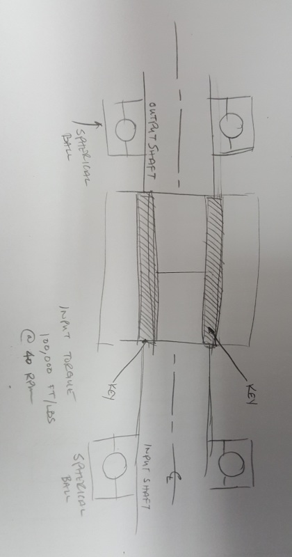
I am working on a rigid coupling that connects a gearbox to a driven shaft.

The shaft being coupled is a 10.125" Dia shaft (4140 @ 200-240 Brinell )seeing a 100,000 ft lbs of torque.

The shaft is keyed using a pair of 3.5 x 2.5" rectangular keys made from key steel @ 180 degrees apart.

The Rigid coupling halves (Ductile Iron) house a key each, and are approximately 22" in Diameter, and use (8) 2" Grade 8 bolts.

If I am understanding the power transfer correctly the two keys are carrying the torque transmitted by the shaft, while the rigid coupling bolts and the clamping force is just resisting the resultant separating force created by the keys.

Under that assumption the coupling is significantly over designed, but i am having trouble going through the calculations.

Any assistance would be greatly appreciated.

Macht
 
Replies continue below

Recommended for you

A rigid coupling also carries a substantial moment in attempting to keep the driven and driving shafts aligned, even over changes in operating temperature, and despite manufacturing imperfections that would have the driven shaft orbiting the driving shaft, with their axes parallel or intersecting.

If it's overdesigned by five percent or five thousand percent, no one will ever know.
If it's underdesigned by five percent, everyone will know, and you will be looking for a job.

If it has to fly, it probably shouldn't be a rigid coupling anyway, so as to not overstress the airframe.


Mike Halloran
Pembroke Pines, FL, USA
 
I suspect that the actual torque load on the coupling is relatively minor compared the huge reversing stresses resulting from alignment issues. That is one humongous coupling. It is difficult to imagine the work it must have taken to get the components involved into the absolutely perfect alignment required by a rigid coupling.
 
Got Pictures or drawings ?

Is this a mature design, or FOAK?

Rigid couplings don't tolerate shaft alignment well, at all. Even if they do, the connected shafts and their bearings don't. Sometimes the ends of the driver and driven shafts are quite thin and relatively long and the driver and driven are well separated to provide radial shaft flexibility and thus be kind to the support bearings when the inevitable misalignment occurs. Also with carefully thought out geometry to avoid stress concentrations.

The equal sharing of torque by multiple keys on the same shaft is not realistic, just as load sharing of splines and snug tightened fasteners in a pattern are factored or de-rated .
 
Yes. A drawing or a picture would be very helpful. I am picturing an axial split clam-shell coupling like the ones commonly used on older vertical in-line pumps, only much, much larger. If that is the case, I would think that the keys are not designed to carry all of the normal torque, but the interference fit between the bore of the coupling and the shafts takes the normal torque.

Johnny Pellin
 
This is an existing design that I am looking to understand and optimize for casting.

There are many of these couplings utilized by existing equipment at my company without any recorded failures after many years of use.

JJP your impression of the coupling is spot on, and I was under the same impression that the keys were not carrying all the torsional load. But this began to come into question when I started asking about bolt torque, and achieved torque and prestress during installation of the coupling.

Thank you for your thoughts and suggestions.


20171107_130929_m0almf.jpg
 
Think of what would happen to the keys if the driven shaft were to freeze and 100,000ft-lb of torque is applied? Forget the moments mentioned above for now.
 
"optimize for casting...."

So the original, well proven, trouble free design is machined from a big hunk of steel, and maybe even a forging, not a casting?
Is the hope to use "as-cast?" with little or no machining?
 
The current design is machined from a casting that is manufactured internally.

I think this thread has deviated to far from the intended target.

I'm trying to understand the calculations or assumptions needed to achieve confidence in creating a design based on this one, in the future.

Thanks again for your help.
 
Macht,

Is it possible that there is clearance over the shafts, and that the keys are carrying 100% of the torque? This might account for the shaft mis-alignment everybody is talking about.

--
JHG
 
Maybe the torque is reacted by both the friction from the clamped-on coupling and the keys. You'd then have a sharing of the load and you'd have to look at relative stiffness. My bet would be that the friction load path is stiffer.
 
We had similar couplings on some large Alky contactors. The attached partial drawing shows our example. If I wanted to evaluate the suitability of this coupling for the torque it is driving, I would approach the problem as follows:

Determine the clamping force for each bolt based on the target bolt stress level. (I would use 50% of yield)
Sum up the total clamping force for all of the coupling bolts.
Distribute that clamping force over the area of contact between the coupling and one of the shafts.
Determine the static friction based on the clamping force and the surface characteristics of the coupling bore and shaft surface.
Determine the sliding force based on the maximum torque acting over that same area at the radius of the contact surface.
Compare the sliding force of the torque and the static friction from the clamping force to determine the service factor based entirely on the contact area without consideration of the keys.

I think the coupling should be designed to drive the full torque with a service factor of at least 1.0 based on the clamping force over the contact area and the keys should be a back-up to that.


Johnny Pellin
 
 http://files.engineering.com/getfile.aspx?folder=48623f41-27f0-4a62-84e9-a6d8d70e0269&file=Capture.JPG
"The current design is machined from a casting that is manufactured internally."

So from the finish dimensions you know if a gap remains on each side between the coupling halves when installed and maybe even how the bolts are tightened. I expect it does. Letting bores , shafts and keys wiggle, even a little bit, is just asking for fretting and big trouble down the road.

For a while Honda machined their off road bikes' handle bar clamps such that the gap at the front was NO gap, but would be clamped tight and hard, and the rear would be reduced but not closed when fully tightened. Very secure, minimal fastener bending, quite clever.


regards,

Dan T
 
JJP thanks for the response, I was thinking to follow this line of thinking. I plan on using this method, and ensuring the interference fit is sufficient.

Dan T,

The current design has a 0.002" interference fit so the clamping load can be transferred. So it does mimic the design you referenced.

Thank you all for your help,
Macht
 
Macht,

This looks very interesting. In order to calculate the torque handling ability of the hub I would follow JJPellin's recommendation, however at that size of a shaft a 0.002" interference will be more than adequate to drive that torque. I can tell you from coupling hub design that an interference hub is limited by the stress riser over the key way generated by hoop stress from an interference fit. When in a clearance fit application a hub can be sized much smaller however if vibratory torque is present other problems will occur. So it is a balancing act. I think what you will find is you will easily be able to generate the clamping force and fit required to hold the torque, however in order to use a casting (reduced material strength) you may run into a scenario where you are stress cracking it by merely clamping the hub onto the shaft.

It may be a better design to actually clamp over the keys, this will eliminate the stress riser in the hub key way (and make it less expensive), but could potentially put more stress into the bolts. Then use a special taller key stock with clearance holes to take up the space.

Love to see some pictures of what you come up with.

When it comes to couplings we are always here to help.
 
I am not sure how you can state that the coupling has an interference fit of 0.002". The couplings of this type I am familiar with are bored and fully machined, and then saw cut into two halves. This leaves a generous gap between the two halves and the clamping force is driven by the bolting. Do you mean that the bore was cut for a 0.002" interference before the coupling was split? Or, was your coupling split with a milled joint and then final bored for 0.002" interference, resulting in no gap once fully torqued?


Johnny Pellin
 
Macht,

Looking at your sketch, something occurred to me.

How far are your shafts cantilevered from your bearings? If both shafts have a significant cantilever, you have room for them to strain, without the corresponding high stresses. Is that how rigid couplings work?

--
JHG
 
Status
Not open for further replies.

Part and Inventory Search

Sponsor