AndrewTT said:
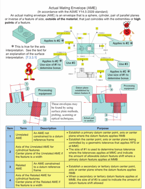
1) Determine the UAME of the hole.
2) Determine the inner boundary that cannot be violated by the surface of this hole (UAME - Position RFS value = inner boundary)
3) Put a gage pin of inner boundary size (calculated in step 2) at true position.
4) If the hole fits over this gage pin then this hole has used less than the allowed position error and is therefore good.
ASME Y14.5.1M-1994 provides basically the same definition as you describe for the surface interpretation of RFS position tolerances applied to holes. Additionally, it states that the surface interpretation shall take precedence over the resolved geometry (axis, in this case) interpretation if the results differ.
I find this rather odd because both ASME Y14.5M-1994 and ASME Y14.5-2009 seem to require the axis interpretation, and in fact don't even mention a surface interpretation, for RFS position tolerances.
I believe it is possible for the results of the two interpretations to differ by up to two times the size tolerance, so I am glad the Y14.5 draft clearly states that there is only a single interpretation for RFS. I wish they would go a step further and eliminate all mention of an axis interpretation for MMC and LMC, but I'm not holding my breath.
As a side note, I believe it's possible to simulate the axis interpretation for RFS position tolerances using hard gaging as follows:
[ol 1]
[li]Get a bushing that has length equal to that of the hole, has a known fixed inside diameter, and has a variable outside diameter that expands to match the UAME of the hole.[/li]
[li]Install and expand the bushing in the hole.[/li]
[li]Get a pin that has outside diameter equal to the bushing inside diameter minus the RFS position tolerance value.[/li]
[li]Attempt to place the pin through the hole in the bushing at true position.[/li]
[li]The tolerance is met if and only if the pin fits.[/li]
[/ol]
pylfrm


![[bigsmile] [bigsmile] [bigsmile]](/data/assets/smilies/bigsmile.gif)