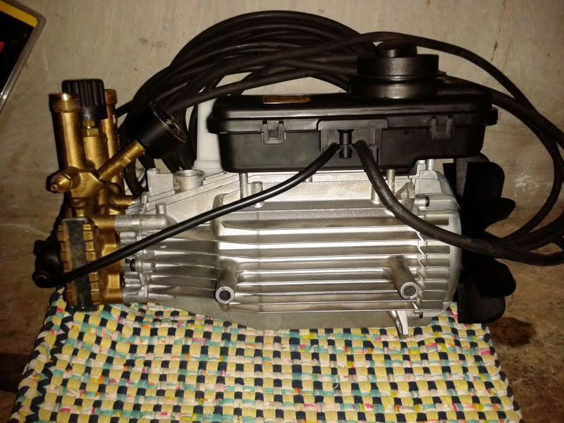
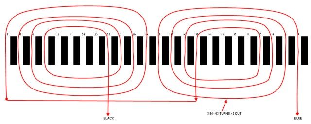
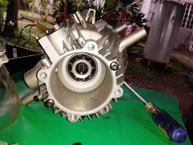
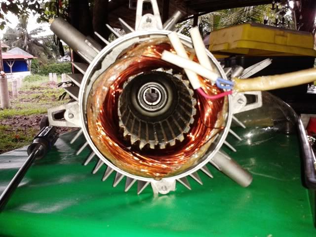
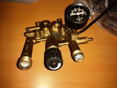
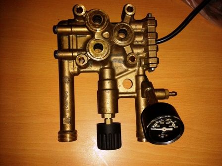
I have confirmed that a PD (positive displacement) pump is a constant torque device. The constant torque motor redesign for 60hz will provide an increase in power equal to that required by increasing the pump speed. Modification of the pump will not be required.
Hi Ray. I will respectfully disagree on this point.
The volume FLOW rate Q increases according to speed (as I had stated). That much should be obvious thinking about the way a piston pump works.
The Fluid Horsepower or Brake Horsepower is given by
BHP = DP*Q
(That should not be a point for dispute. Electrical types may think of that as similar to P = I*E)
We cannot predict change in BHP with speed without knowing something about the system that the pump is attached to (as assumption about DP vs Q characteristics).
The only way to get BHP increasing by 20% when Q increases by 20% for a fixed system as you suggested would be if DP does not change with Q. I hope you'll agree that cannot be correct (would you expect resistor voltage to stay constant when we increase the current?).
You earlier made a statement that you expected P to go up by 1.2^3 for a fixed fluid system when you thought it was a centrifugal pump. To make such a statement requires an ASSUMPTION about the fluid system to which you connect the pump. The particular unstated assumption required is that the fluid system obey DP~Q^2. (Think about it, you cannot obey Q~N, DP~N^2 and P=DP*Q ~ N^3 without also satisfying DP~Q^2).
If we make the same ASSUMPTION for the pd pump, we would come up with the same conclusion. i.e. if we increase pd pump speed by 1.2 when connected to a fixed system which is ASSUMED to obey DP~Q^2, then the power must go up by
P~Q*DP
P~N*N^2
P~N^3
QED. All we needed to get there was to start with was Q~N which is true for PD pump and add an assumption about the system which we chose to be DP~Q^2.
The assumption DP~Q^2 system characteristic happens to be true for closed loop systems whose pressure drop is dominated by head loss from turbulent (vs laminar) flow. When you get into other flow regimes (laminar) it does not apply. When you have open loop system like pressure washer, with possible differences in elevation and velocity at entrance and exit, also does not strictly apply. With more info about orficie and entrance and exit conditions we could do better, but DP~Q^2 is a start and a traditional one at that.
Your reaction might be:
"but wait Pete, those relationships P~Q, DP~N^2, P~N^3 are called "centrifugal pump laws" and so do not apply to PD pumps". It is true but in a different context. . When you ask a fluids guy what those relationships mean, he will tell you that they are NOT intended for predicting change of
individual operating points with speed without knowledge of connected system (that would be folly.... operating point is intersection of pump curve and system curve and we CANNOT determine it without knowing or assuming something about the system curve). What those relationships are intended for is to map
an entire pump curve from one speed to another. That particular mapping process applies to centrifugal pumps and not to pd pumps whose ideal curve is much simpler: a vertical line on DP vs flow graph.
In summary DP~Q^2 is an assumption. It is not perfect and could certainly be refined for orifices and entrance/exit conditions with more info. If we are going to predict change in BHP with change in speed for either type of pump (centrifugal or pd), we need info or assumption about the system. For both type pumps, we can predict BHP~N^3
if and only if we assume the pump is connected to a system which obeys DP~Q^2
=====================================
(2B)+(2B)' ?
