Continue to Site

Eng-Tips is the largest engineering community on the Internet

Intelligent Work Forums for Engineering Professionals

  • Congratulations waross on being selected by the Eng-Tips community for having the most helpful posts in the forums last week. Way to Go!

Requirement of SC bolts in Flange Plate MC under Gravity Loads

Status
Not open for further replies.

ryan89

Structural
Oct 27, 2011
5
I have a heavily loaded cantilever beam framing into a column with a bolted flange plate connection. The loading is pure gravity (no load reversals) and all holes are standard size. I am concerned about the potential additional deflection that may occur due to bolt slip. The cantilever beam supports two floors and excessive deflection may cause unacceptable slope to the floor and/or excessive cracking of the slab.
My questions are the following:

Are these type of connections usually specified as slip critical or bearing? What specific type of conditions or rules are used to determine whether these conditions should be designed as bearing or clip critical?

How much joint rotation would be expected due to bolt slip in bolted flange plate connections? Is there a reference/calculation/guide I could follow to calculate this?

If indeed slip critical designed bolts are recommended, are there some measures that could be undertaken to limit rotation without using slip critical bolts (for example increasing number of bolts)?

I apologize in advance if this question has already been asked somewhere. So far I was not able to find answers for this particular condition through searching the forum.
 
Replies continue below

Recommended for you

SlieRuleEra,
Yes I have read this article, and many similar articles. I guess the issue I have is with the requirement when:

"Joints in which slip at the fraying surfaces would be detrimental to the performance of the structure (e.g., sensitive machinery"

If the joint were to slip the beam deflection increases. How much I am not sure. I would imagine this is mostly a potential issue for cantilever beams which have only one support rather than moment connection in general. One could argue that a sloping floor is detrimental to the performance of the structure from a serviceability standpoint.

What are your thoughts?
 
SlideRuleEra's PDF is helpful, and it confirms my thoughts that slip-critical connections are not needed as commonly as some engineers believe. If you are concerned about deflection for the stated reasons, it might be worth simply upsizing your beam slightly to further reduce your expected deflection. The slight increase in beam weight should prove less costly than switching to slip-critical connections, and will likely also be more effective in lessening your deflection.
 
I don't specify "slip critical" connections. I may design them that way, but I would call them out as connections with pretensioned bolts.

Some thoughts on this:
1) Bolted end plate moment connections are usually designed considering the shear resistance only for the bolts on the compression side of the connection.
2) There is some inherent conservatism in this assumption which probably helps prevent slip for connections that were design as Slip Critical.
3) If you were to get some shear slip, that wouldn't really change the angle of rotation at the support.
4) Of course, you would want to make sure this is a Fully Restrained moment connection (i.e. and extended end plate) rather than a Partially Restrained one (flush end plate). Because, that would greatly affect the expected rotation at the support.
5) I have used a "haunched" end plate moment connection at times to reduce the stress at the connection. Though that was in the post Northridge days when you had to do a lot of goofy things to demonstrate that the hinge would not form at the column.

 
Realistically, on a bolted moment end plate with the plate vertical, bolts horizontal, the bolts are going to slip to the bottom of the hole on the support / top of the hole on the cantilever during the erection process unless you get very creative and hold the beam up to center the bolts while you are tightening them. Once they settle to the side of the hole no amount of force is going to cause them to slip further without deforming the connecting steel itself. You would thus end up with an extra 1/8-1/4" of concrete in your floor slab due to the top of the beam not being quite as high it is was theoretically envisioned.
 
JoshPlum & ajh1

I appreciate these responses, they are very helpful, however, it appears references are being made bolted end plate moment connections, while my question is about flange plate MC only because end plate connection is not possible in this case. Might these suggestions be because bolted end palte MC are the preferred method of connection? I would agree that there is not really any need for slip critical in end plate MC.

Nor Cal SE

That is a good idea to increase beam stiffness. This would imply that bolt slip would cause a small tip deflection. How would you evaluate this to confirm this assumption? Would you say bolt slip may cause 1/16" (bolt hole tolerance) deflection over a distance equal to the beam depth? I have yet to come across something technical to estimate the impact of this rotation. Or am I being overly conservative?

 
Ryan89, though I haven't necessarily analyzed a situation quite like this myself, I think the method you've described is a decent way to start, provided you do not get overly conservative results (in my opinion, if results show you have to double the beam weight, then the analysis method is much too conservative, but that's more of a "gut-feel" thing than anything scientific).
 
Ryan89 -

Sorry about that, I completely misread your original post. Not sure how I came away thinking this was a Bolted end plate... Must be Monday!

You should be able to calculate the rotation for slip based on the difference between bolt and hole size. Assume the bolt is centered in the hole when placed and tightened, then top bolts slip away from the column and bottom bolts slip towards the column.

Rotation angle is approximately equal to ArcTan (2*Delta/d_beam).... Where Delta is the assumed bolt slip and d_beam is the depth of the beam.

However, my sense is that you would not need to assume this extra deflection if you designed the connection as slip critical.


ryan89 - Concur with Nor Cal SE to select a beam with increased moment of inertia to decrease deflection.

For potential slip distance, I take into account the number of bolts that make up the connection. For example, you mention a bolt hole tolerance of 1/16". For multiple bolts, there is only a small chance that all holes will line up precisely to allow 1/16" potential movement. More than likely there will be an interference with one or more bolts well before 1/16" of slip. Not a scientific way to look at it, but, IMHO, probably somewhat true.

[idea]
[r2d2]
 
Thanks Nor Cal SE and JoshPlumb for those tips. Very helpful


SlideRuleEra - I would agree that it is not very likely that all bolts will line up perfectly in the centre of all holes. I am at a loss however in how one would determine the impact on the reduction of slip movement as the row of bolts increases. Would you say this is more of a judgement call or based on experience?

Based on this, I would assume a connection with sufficient amount of bolts may have negligible slip movement, although not sure how this could be determined.
 
ryan89 - I have not come across a multi-bolt connection that showed any signs of slipping... not on bolted bridge structural steel, not on the large amount of heavily loaded structural steel at our electric generating stations. I know that we have not used slip-critical connections at our new generating stations. IMHO, I'd have to say whether a bolted joint will slip and how much is a judgement call, backed up with experience that slippage is not likely (for connections with multiple bolts).

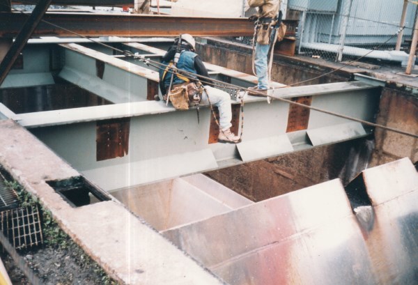
I have used slip-critical connections on my own designs only once - the replacement and upgrade of structural steel for a railcar coal loader. This type unloader is essentially a ground level railroad bridge over a pit. The steel supports some of the heaviest locomotives and fully loaded rail coal cars made. While on the steel, the loaded coal cars are "aggressively shaken" to ensure all the coal onboard is bottom-dumped into the pit. Because of the heavy loads, vibration, and the potential consequences to the CSX trains from connection slippage during use, I considered slip-critical justified.

Slip_Critical_Connections-1_oovh4l.jpg


[idea]
[r2d2]
 
In the situation described here, your potential deflection issue is essentially geometric. I doubt you can depend on tightened bolts not to move, slip critical or not. I would look at either welding the connection or using pins which are driven into the holes, which may require some reaming to align the holes in both members. And you should consider initially setting the end of the cantilever a bit high.

I experienced a similar situation once, where pins were being used in an architecturally exposed canopy. The erector used undersized pins (or maybe oversized holes, I forget), and the resulting deflection was noticeable. When the correct size pins went in, all was good.
 
Status
Not open for further replies.

Part and Inventory Search

Sponsor