Continue to Site

Eng-Tips is the largest engineering community on the Internet

Intelligent Work Forums for Engineering Professionals

  • Congratulations waross on being selected by the Eng-Tips community for having the most helpful posts in the forums last week. Way to Go!

Required Wall Thickness of Finished Bend

Status
Not open for further replies.

SmallInfo

Petroleum
Oct 30, 2017
104
Greetings!
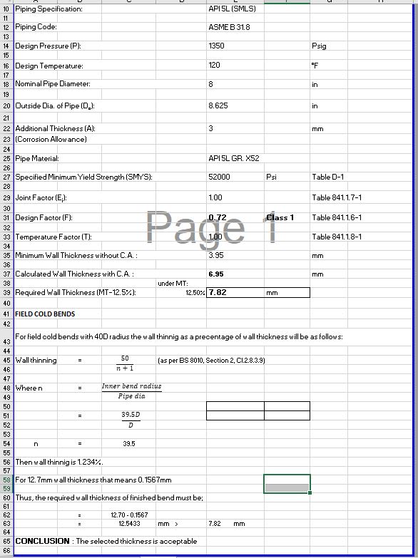
I am provided this calculation sheet for required wall thickness of finished cold bend but can't figure out from where the value 39.5 is taken and this calculation is for 8 inches Dia. why in row no. 58 its saying 12.70 wall thickness when we calculated wall thickness of pipe in above calculation in row 39 is 7.82 mm.
Kindly help me understand this.
Thanks
cold_bend_thickness_lug2ew.jpg
 
Replies continue below

Recommended for you

The bend in question is a 40D cold bend if the inner bend radius is 39.5D, that sounds like a 'rule of thumb' type value for cold bending, see this old thread:

In your sheet the 7.82mm (0.307") is the required minimum nominal wall thickness, 12.7mm (0.500") is the selected nominal wall thickness (Sch 80/XS).
 
B31.8
WT = P x OD /2 /SMYS / DF
1350 x 8.625 /2 /52000 /0.72 =0.155 inches
0.155 inches x 25.4 mm/inch = 3.95 mm Note: not 39.5

+ CA = 6.95mm

6.95 x 1.125 wall increase for max negative wall thickness fabrication tolerance = 7.82mm
Note: It is not correct to increase wall thickness under B31.8 for pipe fabrication tolerance.

BS 8010
Note: IT is not correct to increase wall thickness under BS 8010 if Pipeline Design Code is to B31.8
B31.8: 8" pipe is permitted to be bent to 40 x OD radaii without consideration of wall thickness reduction

B31.8 REQUIRED WALL THICKNESS IS 6.95mm


Einstein gave the same test to students every year. When asked why he would do something like that, "Because the answers had changed."
 
Required Minimum wall thickness is 6.95mm
Required nominal wall thickness is 7.82mm
It all depends on how you write the PO.
This is 8sch40 to me.
I hope that you have a good inspection program, with a CA nearly equal to the required wall localized corrosion could ruin your day.

= = = = = = = = = = = = = = = = = = = =
P.E. Metallurgy, consulting work welcomed
 
Ed, good point about the CA. There appears to be some benefit to having a good corrosion treatment program, if not a liner.

B31.8 has no definition for "nominal wall thickness". I believe you can find a committee interpretation confirming that.


Einstein gave the same test to students every year. When asked why he would do something like that, "Because the answers had changed."
 
You have to go back to the pipe specs for nominals, and that is where the -12.5% wall tol is from also.

= = = = = = = = = = = = = = = = = = = =
P.E. Metallurgy, consulting work welcomed
 
That's correct, however it is a manufacturing allowance only. Nothing to do with B31.4 or .8 allowable operating pressure or required wall thickness calculations. The potential for (-) fab tolerance and the necking of cold bends of radaii allowed in B31.4/8 are all included in the safety factors of the DF.

Einstein gave the same test to students every year. When asked why he would do something like that, "Because the answers had changed."
 
GBTorpenhow
Thank you so much one more question please
If n = inner bend radius/pipe dia then should not it be 39.5/8 = 4.93? or I am misunderstanding something
 
1503-44
Thanks for guidance
Note: It is not correct to increase wall thickness under B31.8 for pipe fabrication tolerance.
Can you please elaborate it more?
 
EdStainless
Thank you so much, not sure what inspection plan client will follow
 
An "inside radius" is a line from the center of the circle to where it first contacts the pipe OD.

I will look for the B31.8 committee clarification on the subject.

Einstein gave the same test to students every year. When asked why he would do something like that, "Because the answers had changed."
 
Small info - You don't really say what your role is or company here as there are so many things wrong with this spreadsheet it's untrue.

X52 SMYS isn't 52,000 anymore, it's now 360 MPa (52,200) Not much difference but get it right.

Whilst it is up to you, B 31.8 doesn't require the manufacturing tolerance to be taken into account. It and B 31.4 are the only codes I know which do this.

Definition in 804.4

nominal wall thickness, t: the wall thickness computed by
or used in the design equation in para. 841.1.1 or A842.2.2
(a) in Chapter VIII. Under this Code, pipe may be ordered
to this computed wall thickness without adding allowance
to compensate for the under thickness tolerance permitted
in approved specifications.

So 7.92 would be a good choice of wall thickness IMHO. So where has 12.7mm suddenly come from?

In calculating n as 39.5 someone is being ridiculous to compensate for the mid point of the bend vs the inner radius. Just use 40.

But this whole bend thinning calculation is simply never done for 40D bends. 5D and 10D maybe, but not 40D cold bends.

Is the intention just to use this pipe for cold bends? or the whole pipeline? Welding loads of 12.7 to 7.92 will be very difficult and costly and no one will thank you

Will be interesting to see your reply.

Remember - More details = better answers
Also: If you get a response it's polite to respond to it.
 

LittleInch
First of all thanks for writing this detailed reply, it really needs a lot of time.
I am mechanical engineer in a design company but my work is mostly dealing with vendors but sometimes whenever any of our design engineer resigns, my company asks me to performs these calculations.
I have some questions based on your writing:
1) How you calculated 7.92?
2) If this calculation is not done for bend thinning then how to calculate bend thinning, can you please guide with a short example?
4) We will be using same pipeline for cold bends.
5) Can we take pipe thickness 6.95 if MT12% is not required in B31.8?
 
After reading every Interpretation this morning. There it is.
Hiding in plain sight, in B31.8 itself.

Look at the definition of "F" the design factor (my DF above).

B31.8 said:
Paragraph 841.1.1 In setting the values of the design factor, F, due consideration has been given and allowance has been made for the various underthickness tolerances provided for in the pipe specifications listed and approved for usage in this Code.


Einstein gave the same test to students every year. When asked why he would do something like that, "Because the answers had changed."
 
Minimum Radius of Bend
40D is even greater than what's (30D) required for 20"+ pipe. See subparagraph (2)

Table 841.2.3-1 Pipeline Field Cold Bend
Requirements Minimum Radius of Deflection of Bend in Pipe

Nominal Pipe Size Axis, deg [see 841.2.3(a)(3)]
Smaller than NPS 12 (DN 300) 841.2.3(a)(4) 18D

NPS 12 (DN 300) 3.2 18D
NPS 14 (DN 350) 2.7 21D
NPS 16 (DN 400) 2.4 24D
NPS 18 (DN 450) 2.1 27D
NPS 20 and larger (DN 500) 1.9 30D


Einstein gave the same test to students every year. When asked why he would do something like that, "Because the answers had changed."
 
All the Calculations that you need to do are in my post above 15 Feb 23 15:08

Einstein gave the same test to students every year. When asked why he would do something like that, "Because the answers had changed."
 
1503-44
Thanks, now its clear for wall thickness, can you please also make it clear for Wall Thinning Calculation?
 
The only time I've ever done wall thinning calculations is when calculating "mother pipe" for use in induction bending of 5D or 3D bends. Then you get to about 8% wall thinning. I've never seen it done for 40D cold bends - just negligible.

I took 7.92 as the nearest wall thickness to the t + CA which is in common use - 0.312"

You could use 7.04mm, but I don't think it's a "common" size. So yes, you could use the nearest practical size to 6.95mm and be in accordance with ASME B 31.8 without adding negative mill tolerance. As said, B31.4 and 31.8 are the only two pipeline codes I've ever seen which do this, so be careful if you're using other codes.

The standard wall thickness in API 5L are detailed in ASME B 36.10M. They used to be in API 5L, but got shifted a few years ago. I.e. a wt of 6.95 is not commercially available.

Remember - More details = better answers
Also: If you get a response it's polite to respond to it.
 
SmallInfo said:
If n = inner bend radius/pipe dia then should not it be 39.5/8 = 4.93? or I am misunderstanding something

For convenience, bend radii are typically expressed as a multiple of the nominal diameter, e.g. a 40D bend in 8" NPS pipe would have a centerline radius of 40*8"=320", but the same 40D bend in 4" pipe would have a centerline radius of 40*4"=160".

If the centerline bend radius is 40D, then the inner bend radius is 39.5D, and n = (39.5D)/D = 39.5, for any pipe size. Hence my deduction that this sheet is built to check a 40D bend.

I cant answer the question why 40D is used, it does seem odd because as 1503-44 quotes above, B31.8 allows a much sharper cold bend, up to 18D for 12" NPS or smaller, without any extra calculation or consideration.

You can always exceed code requirements due to client requirements or internal standards, but in this case using a large CA, including a 12.5% mill tolerance, and an allowance for estimated wall thinning pushes you from STD into XS, which probably represents a significant increase in material and welding cost.

 
I think I recall from ancient times, there once was a minimum 40D bend radius for 20" pipe and above, but do not quote me on that.

Einstein gave the same test to students every year. When asked why he would do something like that, "Because the answers had changed."
 
Status
Not open for further replies.

Part and Inventory Search

Sponsor