Eng-Tips is the largest forum for Engineering Professionals on the Internet.

Members share and learn making Eng-Tips Forums the best source of engineering information on the Internet!

  • Congratulations dmapguru on being selected by the Eng-Tips community for having the most helpful posts in the forums last week. Way to Go!

Relay Schematic Question

Status
Not open for further replies.

NathanHussey

Mechanical
Joined
Jul 9, 2012
Messages
2
Location
AU
Hi guys,

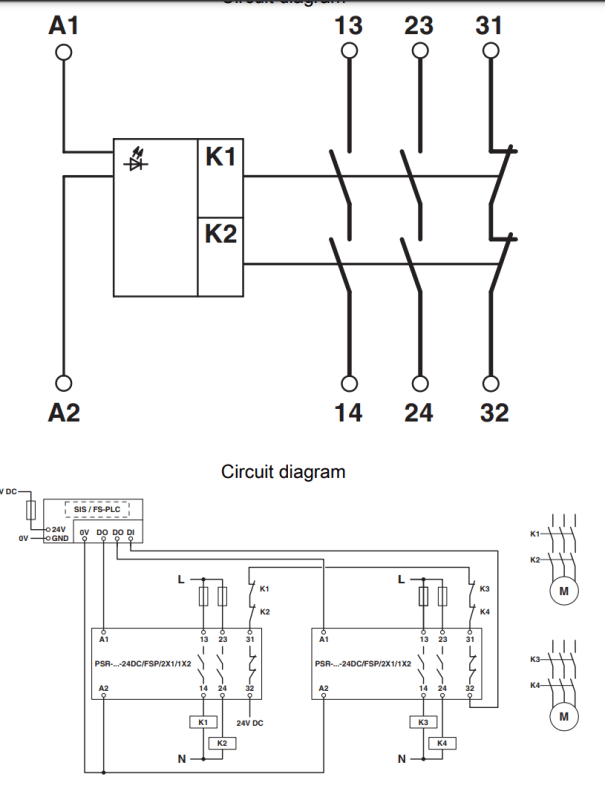
Hoping you can help answer a simple question for me on the schematic attached/below. A1/A2 are coil inputs to the relay. 13/14, 23/24 are K1 & K2 contactors, normally open.
- what is 31/32?
- Why would we have both K1 & K2 contactors to single motor as shown, if they are activated by the same input to the relay?

Capture_dmzpsu.png
 
Ah that makes sense - the 24V circuit through the 31-32 contacts tells if both relays are in the de-energized position; if either one is in the energized position then the 24V circuit is open.

This could let the control circuit detect when one relay has failed in the energized position, such as IRstuff indicates, via welded contacts. Therefore, before powering the motor the control circuit has a test to see if the relays are in the "OFF" position. When the relays are energized, the 24V circuit can tell that at least one relay worked by going open. Then, when the relays are de-energized, if the 24V circuit does not close then at least one relay has failed in the energized position.

Electrically, its a NOR gate.
 
This is a safety relay. If rusty memory serves me right, this looks like a Phoenix Contact relay diagram.

Is this motor multi-phase power? Running multiple phases through a single relay is the most common case for multiple relay contacts to a single load.

31 and 32 are confirmation current contacts. When the relay is open, they provide a signal to the PLC which confirms that power on the K1 and K2 contacts is disconnected.
 
Status
Not open for further replies.

Part and Inventory Search

Sponsor

Back
Top