Tek-Tips is the largest IT community on the Internet today!

Members share and learn making Tek-Tips Forums the best source of peer-reviewed technical information on the Internet!

  • Congratulations MintJulep on being selected by the Eng-Tips community for having the most helpful posts in the forums last week. Way to Go!

Reason for shaft breaking prematurely on 9 stage MSN type Flowserve pump at throttle sleeve?

Status
Not open for further replies.

Mech5656

Mechanical
Joined
Aug 2, 2014
Messages
127
Location
US
Hello,

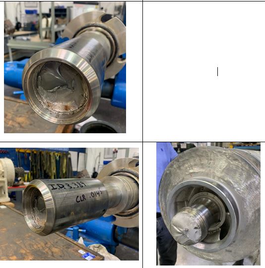
We received a pump because it failed prematurely due to shaft breakage. After disassembly, we found that shaft was broken at throttle sleeve corner. Pump was last repaired about a year ago and shaft was not replaced. Can you tell what can be the failure reason? The pump ran for some years before this happened.

Capture_xevpoe.jpg
 
Step 1 of any investigation will need a detailed look at the pumps operating conditions - flow, head compared to the pump curve and its designed duty point, vibration levels etc combined with an analysis of the failure mode.


It is a capital mistake to theorise before one has data. Insensibly one begins to twist facts to suit theories, instead of theories to suit facts. (Sherlock Holmes - A Scandal in Bohemia.)
 
VFD? Cyclic operation? Any vibration readings?

= = = = = = = = = = = = = = = = = = = =
P.E. Metallurgy
 
Can you attach the pictures as files so that we can zoom in on them. The images in the post are scaled back.

Any drawings or dimension / torque / rpm / shaft power?

Is there any sort of flexible coupling here?

This seems to be a shaft with a screwed sleevee right?
Was this a taper fit coupling?
How was the sleeve tightened?

If the alignment is not correct to microns, you will fail a shaft like this. IMHO.

Remember - More details = better answers
Also: If you get a response it's polite to respond to it.
 

Agree with above posts. The break seems in itself to perhaps be initiated by material fault or surface damage.

 
Has Flowserve been contacted, it would be a good place to start.

It is a capital mistake to theorise before one has data. Insensibly one begins to twist facts to suit theories, instead of theories to suit facts. (Sherlock Holmes - A Scandal in Bohemia.)
 
Pump had no vibration issue before shaft failure.
Pump was running within 15% of BEP flow during operation.
Pump has a sister spare pump on side that runs alternatively with this one. So they are switched to make sure they are both operationally good.
Pump stopped in 2-3 seconds after failure.
Shaft did not show any other crack during in liquid penetrant test.
 
A 9-stage pump has quite a long casing and will be very sensitive to misalignment due to pipe strain or soft foot. This won't necessarily cause vibration. The recent service would make me suspicious as that opens the possibility for an incorrect alignment.
 
What was the condition of the bearings, wear rings, and balance disk/drum?

Walt
 
I don't know much about pump shaft sleeves and probably don't have much to contribute. But I'd like to ask how is the sleeve affixed to the shaft... is it interference fit, or is it threaded (I think I see some threads there).

=====================================
(2B)+(2B)' ?
 
As Artisi stated, an investigation is needed to take a detailed look at the pump operating conditions.

Do you have a scenario where reverse flow occurred that causes a pump's impeller and shaft to turn backwards and the pump suddenly kicks on? You then have a stressed or broken shaft. This scenario occurs when check valves upstream are partially or completely plugged, or otherwise not functioning properly.

 
Thank you all for your replies. I appreciate, read and consider every comment. I am lucky to have resources like yourself.

This shaft was broken at threaded areas of throttle sleeve. Wear ring running clearances are not too high (0.017"-0.020")

Here are detailed pump operating conditions:

suction pressure : 30 psig
discharge pressure 1500 psig
temperature 190 F
shaft rpm 3560
fluid produced water
 
Mech5656.
That info, doesn't really add anything. You need to establish the mode of failure, from there you can start looking into what operating condition resulted in the failure.
I always used our State Railway authority for complicated shaft failures, an area in which they have first class experienced due to the large numbers of shafts/axles in their rolling stock.

It is a capital mistake to theorise before one has data. Insensibly one begins to twist facts to suit theories, instead of theories to suit facts. (Sherlock Holmes - A Scandal in Bohemia.)
 
Is it possible that a shock load created by water hammer from a discharge line check valve suddenly slammed shut during a second pump switch. These pumps create very high pressure and volumes at 3560 rpm. The internal rotor clearances are usually very small to produce high hydraulic pump efficiencies and normally won't tolerate any misalignment between rotor and casing. All rotors are balanced for their specific rpm. Any deviation of the rotor would normally show as rub marks at impeller wear rings against case rings. Or in the area of center stage piece.
 
I am certainly not an expert on shaft fatigue and the photos supplied are not that inclusive, but what I see is a gradual operational failure (fretting and staining) with a final overload failure (clean fracture).

It is a capital mistake to theorise before one has data. Insensibly one begins to twist facts to suit theories, instead of theories to suit facts. (Sherlock Holmes - A Scandal in Bohemia.)
 
Hi

Look at this site it might help
A question if I may, the shaft failed in the threaded region of the sleeve you say, so are the shaft and sleeve screwed together at this point? If so I would be looking at the threaded areas on the shaft because the base of the thread could be the high stress point for a crack to initiate.

“Do not worry about your problems with mathematics, I assure you mine are far greater.” Albert Einstein
 
Status
Not open for further replies.

Part and Inventory Search

Sponsor

Back
Top