nivoo_boss
Structural
- Jul 15, 2021
- 132
Hey everyone!
I'm designing an RC slab that is preferably 220 mm thick and is supported by RHS steel columns mid height. All the columns are at the edges of the slab, the mid columns don't continue through the slab. Now I know punching shear is probably the most important aspect of the slab design on mid columns, but what about the areas on edges where the columns should support the slab?
The first issue is - how should I model it? Should the joint be pinned where the slab is supported mid columns? I'm not even sure how to input that into to the model. When detailing it as something I drew below, it should be pinned.
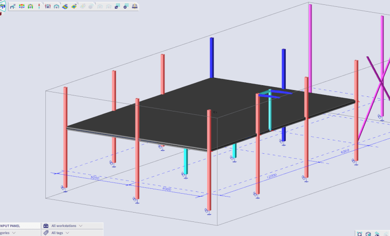
This a screenshot from the model:

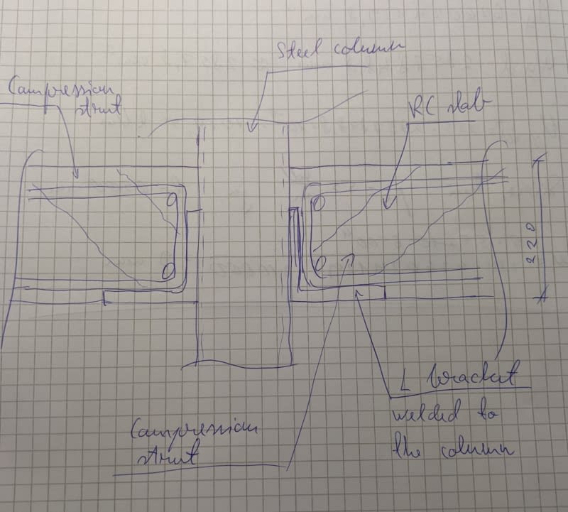
And this is sketch of the detail. I've seen something like this before.

As for the column, is it correct to assume that shear is transferred to column via this compression strut I sketched? How should the L bracket be designed?
I'm designing an RC slab that is preferably 220 mm thick and is supported by RHS steel columns mid height. All the columns are at the edges of the slab, the mid columns don't continue through the slab. Now I know punching shear is probably the most important aspect of the slab design on mid columns, but what about the areas on edges where the columns should support the slab?
The first issue is - how should I model it? Should the joint be pinned where the slab is supported mid columns? I'm not even sure how to input that into to the model. When detailing it as something I drew below, it should be pinned.
This a screenshot from the model:

And this is sketch of the detail. I've seen something like this before.

As for the column, is it correct to assume that shear is transferred to column via this compression strut I sketched? How should the L bracket be designed?
