Continue to Site

Eng-Tips is the largest engineering community on the Internet

Intelligent Work Forums for Engineering Professionals

  • Congratulations KootK on being selected by the Eng-Tips community for having the most helpful posts in the forums last week. Way to Go!

RC slab supported on steel columns mid height 2

Status
Not open for further replies.

nivoo_boss

Structural
Jul 15, 2021
132
Hey everyone!

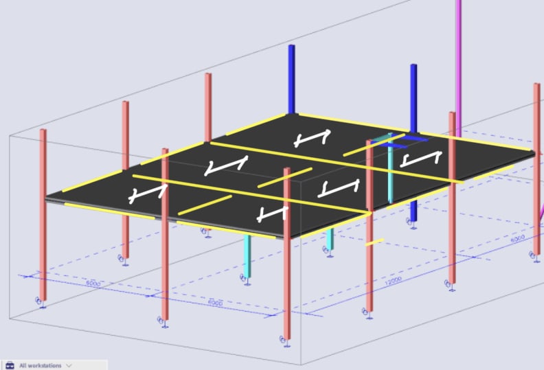
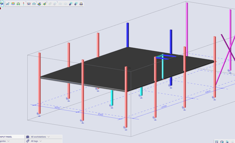
I'm designing an RC slab that is preferably 220 mm thick and is supported by RHS steel columns mid height. All the columns are at the edges of the slab, the mid columns don't continue through the slab. Now I know punching shear is probably the most important aspect of the slab design on mid columns, but what about the areas on edges where the columns should support the slab?

The first issue is - how should I model it? Should the joint be pinned where the slab is supported mid columns? I'm not even sure how to input that into to the model. When detailing it as something I drew below, it should be pinned.

This a screenshot from the model:

slab_on_columns_g0j3ry.png


And this is sketch of the detail. I've seen something like this before.

detail_v1cs8z.jpg


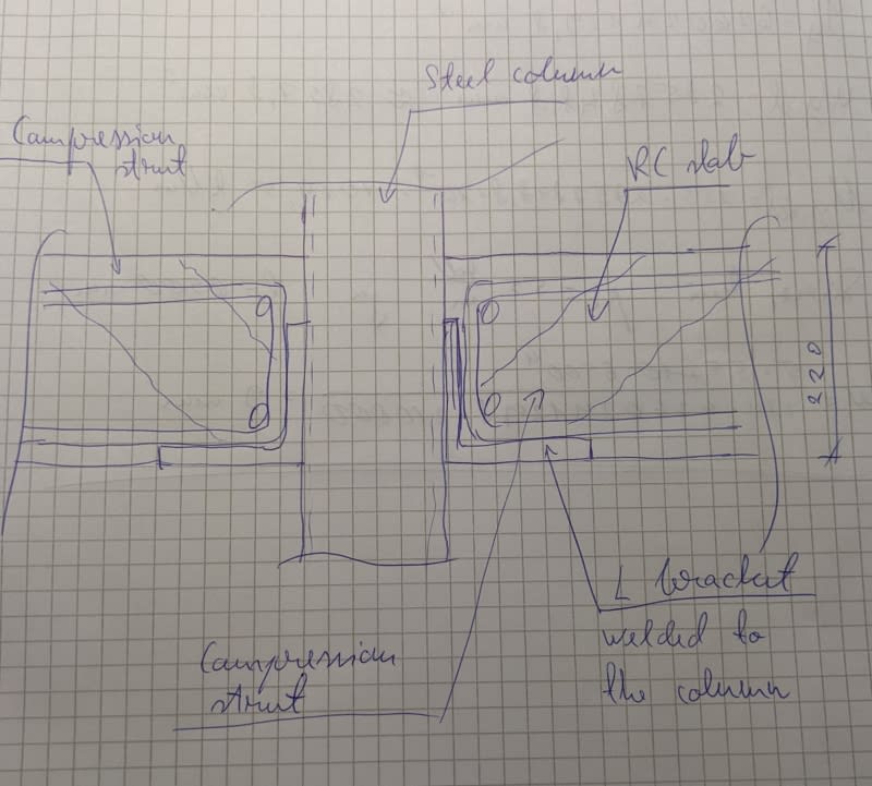
As for the column, is it correct to assume that shear is transferred to column via this compression strut I sketched? How should the L bracket be designed?
 
Replies continue below

Recommended for you

Hi,

Can I just say that I really don’t like the detail. Intuitively it feels wrong to me personally.

Why are you doing a flat slab with steel columns? Can you not frame this out with internal beams and one way slabs? Slimflor beams and decking? How are you achieving tying/robustness/disproportionate collapse? Is there a risk of water getting in there at each support joint?

Once we establish the above, perhaps we can discuss detailing.
 
"Why are you doing a flat slab with steel columns? Can you not frame this out with internal beams and one way slabs? Slimflor beams and decking? How are you achieving tying/robustness/disproportionate collapse? Is there a risk of water getting in there at each support joint?"

Because it just kind of landed on my desk. The steel columns are already manufactured with the L brackets and stirrups welded to them - I think the original design had RC columns but it had these same brackets as well welded to anchor plates cast to the columns. Internal beams I could consider, but the spans seem too long for them, considering it should be a 220 mm thick slab. There isn't much risk of water getting into the joints, it's an office block.

And the detail is in no way final, just a rough idea.
 
nivoo boss said:
The steel columns are already manufactured with the L brackets and stirrups welded to them

Then I think they should cut the brackets off of the columns and weld shear tabs on for some beams. I agree with MIStructe_IRE...this just feels wrong. If you stopped your column and had a top plate, maybe I could see something analogous to punching shear with a flat plate. But this feels like an attempt to reinvent a wheel that has never been perfect anyway (most catastrophic RCC failures seem to be in flat plate) by removing the parts that make it work.

If it just landed on your desk then now is the perfect time to slam on the brakes and get everyone to reconsider it before it goes any further.
 
I don't know, there is a method called lift-slab construction that is very similar to this one. Even the slab and column details are basically the same.
 
Well, I'm not designing a 14 floor concrete building.
 
I suppose it's possible...but I'd likely take a pass on that one if I had an option to do so. I'll watch the thread, though...I'd be happy to learn something about it if others have more to share.
 
Thank god I am not the only one who looked at that and went: nope, not for me.

If you are welding the stirrups to the angle I'm not sure I'd consider that truly pinned unless the angle leg is sized to be flexible(ish), in which case I have more grave concerns (assuming that the HSS isn't (relatively) thin walled that we can get rotation by local buckling, which surely would turn the connection into a pin but see the thing about other concerns above).

I'd also be careful about constructability. You'll need columns / steel structure to stand on its own even without the slabs, which can be done but you arn't showing many (any?) cross members in your schematic. They'll need to be added at appropriate intervals to maintain stability until the slabs are cured. Alternatively, you'll have to rely on temp support throughout construction.

I'd push for a new detail.

EDIT - I see the reference to lift slab construction above. This did remind me of that. But I default to the same thought: not for me. Maybe for more hero like people I suppose.
 
Chalk up another "That gives me the bad feels" vote.

I do understand similar things are done constantly as retrofit solutions, however there are many better ways to skin a cat on a new construction project.

And why would the client already have fabricated columns if the design drawings aren't even complete yet? What are they going to tell say when you need a certain wall thickness but they've already fabricated them with a thinner wall?
 
As I said, the detail is in no way final. The stability of the steel columns is not an issue - the roof is braced during the pouring and I might add some bracing members between the columns.

I mostly would like to know how to approach a detail like this, how to transfer shear around the column from slab to the column etc.
 
"And why would the client already have fabricated columns if the design drawings aren't even complete yet? What are they going to tell say when you need a certain wall thickness but they've already fabricated them with a thinner wall?"

Because this is how construction works sometimes :) Actually, the columns are designed to the slab and live loads, but the slab itself isn't designed yet.
 
OP said:
I mostly would like to know how to approach a detail like this, how to transfer shear around the column from slab to the column etc.

Alright, we'll see if we can't kill this thing by the numbers then.

1) I wouldn't use this connection for punching shear resistance without testing to back it up.

2) If your jurisdiction has requirements for slab integrity steel, take care to arrange your setup such that you meet those requirements somehow.

3) Typical punching shear values assume monster slab flexural stress in the compression zone over the support that will be dubious here. I wouldn't go higher than 2(root(f'c) in this situation.

4) One of the problems with the setup, in my opinion, is that the design for punching shear often assumes simple support at the columns when, in reality, hogging moments at the supports will often be unavoidable. This will definitely be the case at interior column and the slab strips parallel to the building edge at exterior columns. In many ways, as shown below, I think that one would be better of attempting to maintain continuity rather than attempt a bullshit hinge.

5) If you insist on playing the simple support card, your issue du jour becomes the proper anchorage of the bottom steel at the support. Frankly, I'd feel a whole lot better about that if your bottom bars were welded to the angle or the column somehow. That said, with a deep enough slab, wide enough angle bearing leg, and small enough U-bars, what you're showing would probably work by the numbers. You're not wrong about those struts although they seem optimistically shifted towards the column in your sketch.

C01_qbkj3y.jpg
 
6) I don't see you being able to properly mobilize all sides of your perimeter columns-slab connections for this, as you would with a slab gloriously sandwiched between two CIP columns. I'd be studding resistance planes similar to what I've shown below, again at half the allowable stress used at typical, interior, CIP columns.

C01_hhwk3s.jpg
 
As a structural engineer, never be afraid to hold your hands up or slam on the brakes. Don’t go with something that you’ve inherited if you’re not happy with it and never let a client or situation push you into anything you don’t want to do.

I’d really steer clear of this proposal to be honest. The only thing I’ve seen even resembling this has been the lift slabs.. and we’ve all seen what happened there. Don’t reinvent the wheel for a simple office floor on a 6m grid.

Your spans are only 6m. A 200mm UC slimflor beam will comfortably do this with office floor load. Frame it out in steel and we can all sleep!

Out of interest, what part of the world are you in? Is this common in your area?


1FAFE205-F8DA-482B-B920-32A16C241762_mpszbd.jpg
 
Re lift slab...

image_wn0nzt.png


Where was the professional association in this? not doing their job?

Rather than think climate change and the corona virus as science, think of it as the wrath of God. Feel any better?

-Dik
 
"4) One of the problems with the setup, in my opinion, is that the design for punching shear often assumes simple support at the columns when, in reality, hogging moments at the supports will often be unavoidable. This will definitely be the case at interior column and the slab strips parallel to the building edge at exterior columns. In many ways, as shown below, I think that one would be better of attempting to maintain continuity rather than attempt a bullshit hinge."

Yes, the hogging moments there are unavoidable. And for that couldn't I use some extra reinforcement on top of the slab - bars that are parallel to the edge?

"5) If you insist on playing the simple support card, your issue du jour becomes the proper anchorage of the bottom steel at the support. Frankly, I'd feel a whole lot better about that if your bottom bars were welded to the angle or the column somehow. That said, with a deep enough slab, wide enough angle bearing leg, and small enough U-bars, what you're showing would probably work by the numbers. You're not wrong about those struts although they seem optimistically shifted towards the column in your sketch."

I'm not insisting anything. And the U-bars are welded to the column, so the anchorage of the bottom reinforcement should not be much of an issue.

"Out of interest, what part of the world are you in? Is this common in your area?"

In the EU, Estonia. And no, it is not common here, it's the first time I've come across something like this as well, but the original design comes from a reputable company (when the slab was supported by RC columns, but the same way - an L bracket with U-bars welded to an anchor plate installed in the column). And because I'm from Estonia, English is not my first language and some terms might be unfamiliar to me, like slimflor etc :) Although googling them helps and I mostly see what you mean.

EDIT: From KootK's picture "HSS tends to crush under compression load". I think your are thinking in too 2D here :) There is a strip of concrete right behind the column since it's a slab, the columns are 200 mm, so 200 mm away which resist this kind of action. If I would have RC beams between the RHS steel columns, then I might agree with you on this.
 
I’m not sure why they would originally propose RC columns with a steel collar on a new build. However doing this with RC columns (even with collar supports) and doing this with steel columns as you’ve shown are two entirely different things.

Who came up with the idea to use steel columns?! It sounds like a client idea.. I still don’t like it.
 

Eng. nivoo_boss (Structural),

My suggestion will be, analize your model ( FEM ) and see the problems.. The spans are 6.0 m and will transfer huge moment to the perimeter columns.

Your concerns should be punching , servicability of the slab.....

You may look to the past threads and one of them,

thread507-473298


If i were in your shoes, the composite slab would be to go with..

 
op said:
And for that couldn't I use some extra reinforcement on top of the slab - bars that are parallel to the edge?

Sure, that's just what I showed in the sketch that I posted.

OP said:
EDIT: From KootK's picture "HSS tends to crush under compression load". I think your are thinking in too 2D here :) There is a strip of concrete right behind the column since it's a slab, the columns are 200 mm, so 200 mm away which resist this kind of action. If I would have RC beams between the RHS steel columns, then I might agree with you on this.

I was thinking of this mechanism. Once you commit to the angles supporting the vertical load, I feel that logic has to be carried through the entire connection, creating the need for an HSS wall buckling check as shown. It sort of depends on whether you see the slab pushing against the top of the angle or pulling away from it. I'm thinking the latter in light of the potential for hogging moments.

C01_hdcwvr.jpg
 
Status
Not open for further replies.

Part and Inventory Search

Sponsor