Tek-Tips is the largest IT community on the Internet today!

Members share and learn making Tek-Tips Forums the best source of peer-reviewed technical information on the Internet!

  • Congratulations JAE on being selected by the Eng-Tips community for having the most helpful posts in the forums last week. Way to Go!

Rafter and wall plate connection

Kristofer-O

Mechanical
Joined
Jun 20, 2025
Messages
5
Hi guys,

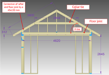
I'm building myself a garage and I wanted to get your opinion on wall thrust and the rafter and wall plate connection. All the dimensions are in mm.
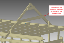
As you see on the picture, I want to connect the rafter to the floor joist using a 45x145 mm material. I was wondering is there a concern that the outward thrust that the rafter exerts wants to bend that piece outward? At the moment I have the collar tie there to prevent the rafters from pushing outward but what would happen if I remove the collar tie? Would then the outward thrust bend the rafters apart?
1750417545759.png

Appreciate all thoughts
 
Here is another option that is a mixture of both. I have seen this done many times in the past 20 years whereas I rarely saw it 30 years ago. Whether you use 1 or 2 top plates depends on whether rafters and joists are aligned. Not aligned is generally 2 layers of plate. The rafter attachment still has to be strong enough since there is thrust. I think there may be a Simpson connector that can make the attachment.


View attachment 14362
This is common in my area. No Simpson connectors anywhere. Have never been able to get the numbers to pan out.
 
The reasons are simple. Because i want to have the "attic" space as high as possible. Also i have all the material already bought and the walls are up and now im in a spot where going back to this standard framing that you propose requires quite a bit of effort. I totally realize that the standard solution with rafters lapped to joist is sturdy and preferred.
So that's why i posted the question that would the solution with the vertical blocks work or what to look out for to make it work.
If we're looking at this sketch:
1750623823082.png

The basic procedure is:
  1. Calculate the thrust/tension force in the horizontal piece.
  2. Design a connection between it and each rafter.
  3. Design the rafter to resist the thrust force and the forces due to dead, snow, and any other applied loads.
  4. Design the vertical piece to transfer gravity and other loads (like wind uplift) to the wall below.
What works and what doesn't work comes down to the location of the horizontal piece (lower is better for less thrust/tension force), member sizes, materials, rafter spacing, and the magnitude of snow and other loads. There's no simple rule of thumb for what works here. Do the calculations and then report back for more meaningful feedback.
 
This is common in my area. No Simpson connectors anywhere. Have never been able to get the numbers to pan out.
I have never calculated one, but have seen it on REALLY old houses and newer ones. Time you put up to 4 toenails into the rafter cut, can't be much strength left. This case may work since the rafter is short.
 
Last edited:

Part and Inventory Search

Sponsor

Back
Top